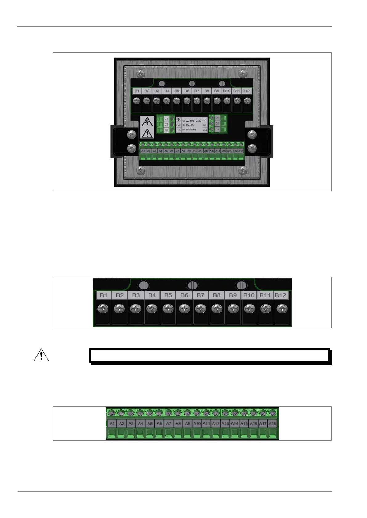
Figure 5: P153 rear view-terminal connection
2.3.3 Terminal Blocks
2.3.3.1 CT connections
P153 devices use terminal blocks as shown below. The terminal block consists of up to 12 x M3.5
screw terminals for CT connections. The CT wires should be terminated with 90° L-shape ring lugs,
with no more than two lugs per terminal.
Figure 6: CT terminal block
Caution: Always fit an insulating sleeve over the ring terminal.
2.3.3.2 Input / Output connections
The terminal block consists of up to 18 x M3 pin terminals used for input/output connections. These
should be wired with 1.5 mm
2
PVC insulated multi-stranded copper wire.
Figure 7: Status and output contact terminal block

 Loading...


