Filter valves
The optional in-line filter valve block set is identical to the air trap valve block set. There
is also a manual valve for air evacuation, HV-301.
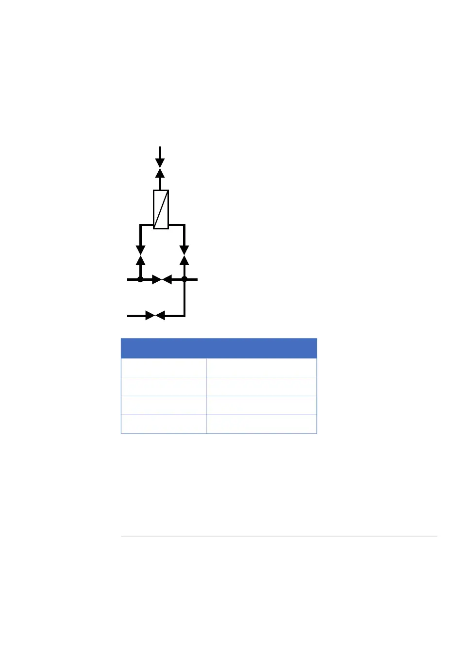
The layout of the filter valves is illustrated in the following diagram.
XV-025
XV-027
HV-301
XV-072
XV-026
Open valve(s)Valve positions
XV-026Bypass (default)
XV-025 + XV-027Inline
XV-025 + XV-027 + XV-072Out_through_drain
HV-301 + XV-027 + XV-072Drain (No flow)
The Drain valve position is used, for example, when the filter housing is emptied before
replacing the filter. The pump(s) must be set to 0.0 l/h when the Drain valve position is
used.
The UNICORN instruction ManFlow must be used when running
Out_through_drain unless the system has a flow meter before the air trap.
However, it is possible to use Flow for short periods of time even if the system
is not equipped with a flow meter.
Note:
ÄKTAprocess Operating Instructions 29-0252-49 AA 67
3 System description
3.4 Optional components