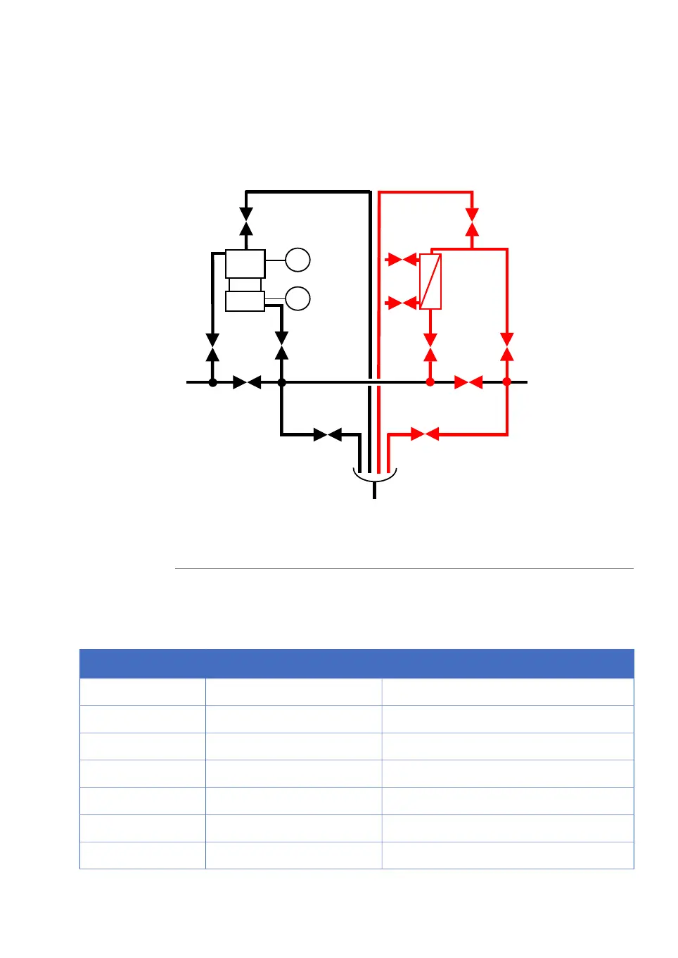
Capsule filter option
The illustration below shows the corresponding air trap and filter block alternative section
of the flowchart if the capsule filter option is selected.
L
L
AT-221
LEH-167
LEL-166
XV-023
XV-021
XV-024
FH-231
HV-301
W
XV-071
XV-022
XV-025
XV-027
XV-072
XV-026
HV-303
HV-302
Black represents standard components; Red represents optional components.
Note:
Process components
The following table lists the process components that are shown in the flow chart.
NoteFunction (qty)Tag
Outlets1, 2
OptionalOutlets3 to 10
Buffer A inletsA1, A2
OptionalBuffer A inletsA3 to A10
Air trapAT-221
Part of system pump B optionBuffer B inletsB1 to B6
Column 1 top connectionC1T
ÄKTAprocess Operating Instructions 29-0252-49 AA 73
3 System description
3.5 Flowchart