4-20 B90 LOW IMPEDANCE BUS DIFFERENTIAL SYSTEM – INSTRUCTION MANUAL
FRONT PANEL INTERFACE CHAPTER 4: INTERFACES
4
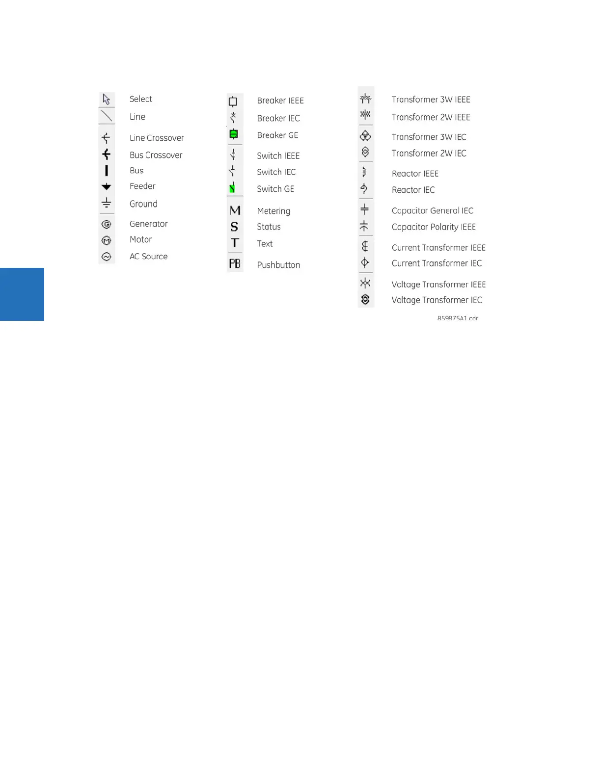
Figure 4-23: Toolbar options for single-line diagram
The letters T, S, B, R, and X next to a controllable element have the following meaning:
• T — The element is "tagged." Local and remote control of the device are inhibited, both open and close. Tripping is
unaffected unless additional logic has been configured.
• S — The position indication of the device is substituted with a manually entered value
• B — Blocking open/close command is bypassed
• R — Autoreclose is enabled and not blocked
• X — The device is out-of-service and control is not available
Single-line diagram example
The following example outlines how to create a circuit breaker diagram, then how to close the second circuit breaker.
The figure shows six switches, two breakers, feeder, and ground.