CHAPTER 4: INTERFACES FRONT PANEL INTERFACE
B90 LOW IMPEDANCE BUS DIFFERENTIAL SYSTEM – INSTRUCTION MANUAL 4-21
4
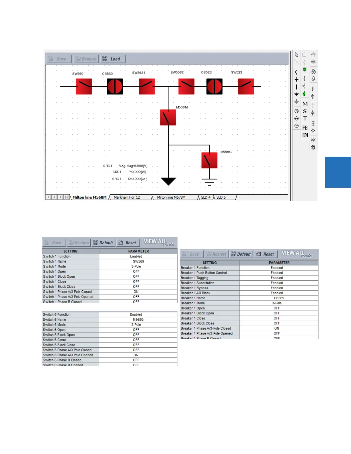
Figure 4-24: Single-line diagram of open circuit breakers
Under Settings > System Setup > Switches and Breakers, enable and name the six switches and two breakers. Switch
M568G has the A/3 Pole Opened on and displays in red on the relay screen.
Figure 4-25: Configure Breaker and Switch settings
In the EnerVista software, open the single-line diagram editor under Settings > Product Setup > Graphical Panel > Single
Line Diagram Editor.
Add the four switches for the top line by clicking the GE switch symbol in the toolbar, then clicking in the window. If the UR
device is not online, the software attempts to connect. Double-click to edit properties. Rotate switches SW569 and
SW5682 to 270 degrees. Rotate switches 5681 and SW523 to 90 degrees.