7-40 170 Series Monitor Revision C
2000947-004
Serviceable Assemblies: Replacing a Front Panel Connector
Replacing a Front Panel Connector
Equipment Required
Screwdriver
Connector (see Table 7-14)
De-soldering tool
Soldering iron
Solder
Procedure
1. Disconnect the AC adapter from the monitor to completely remove power.
2. Follow the instructions for “Removing the Monitor Top Cover” on page 7-19.
It is not necessary to disconnect the cables. You only need access to the front
panel connectors.
3. Follow the instructions for “Replacing the Main Board” on page 7-35. (There is
no need to remove the FECG/IUP Board.)
4. Remove the six screws from the front-end connector shield.
5. De-solder the damaged connector and discard.
6. Solder a new connector in place.
7. Replace the connector shield, main board, and top cover.
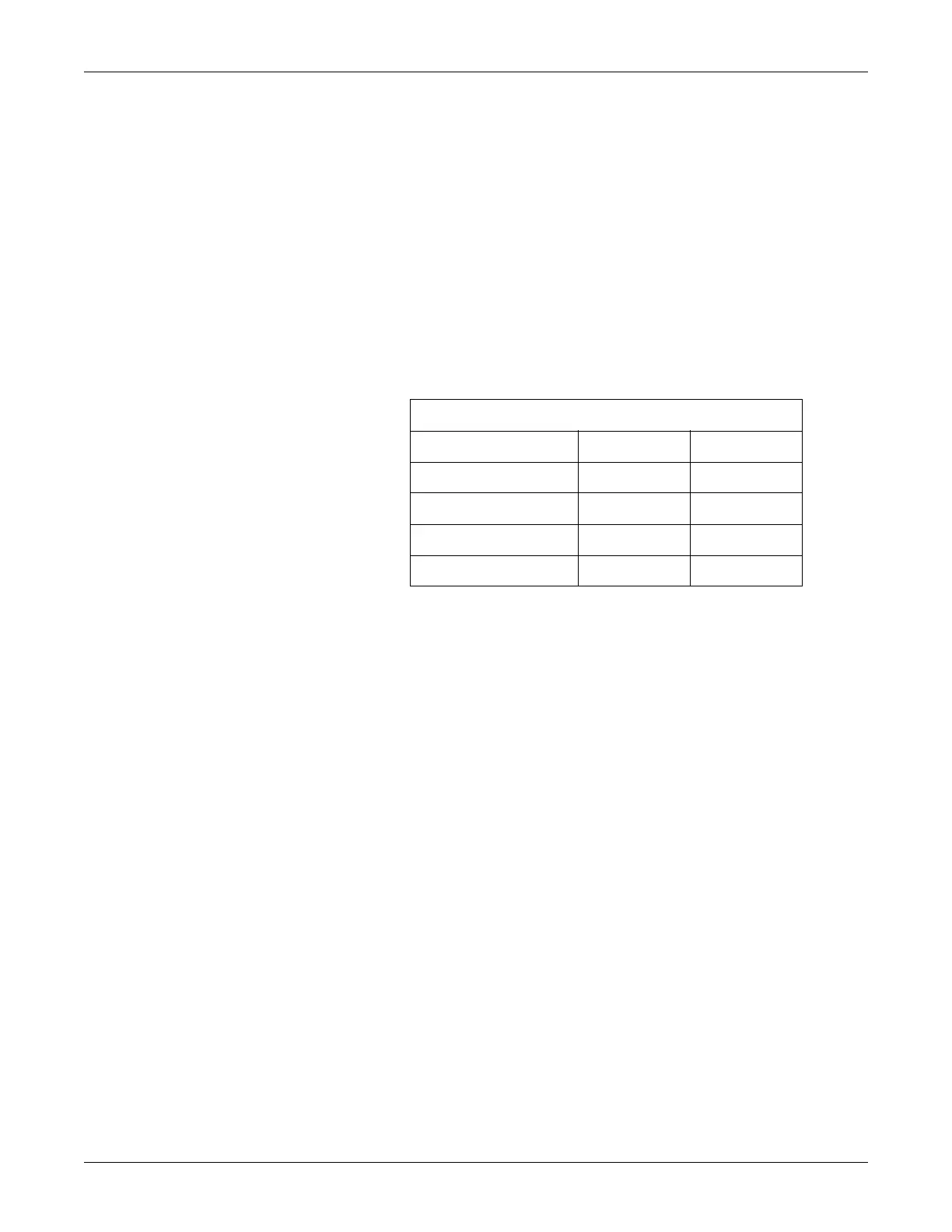
Table 7-14. Front Panel Connectors
Connector Color Part Number
US/US2 Blue 212174
UA (TOCO/IUP) White 212173
FECG Dark Grey 212175
COMBI (US/FECG) Blue and Grey 2003692-001

 Loading...


