3-14 F650 Digital Bay Controller GEK-106310AE
3.1 ENERVISTA 650 SETUP SOFTWARE INTERFACE 3 HUMAN INTERFACES. SETTINGS & ACTUAL VALUES
3
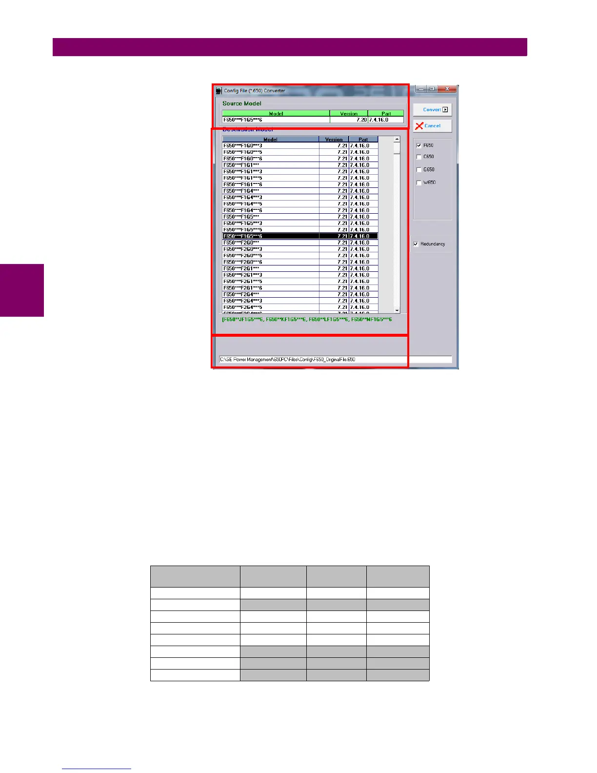
Figure 3–7: CONFIG FILE (*650) CONVERTER MENU
It is possible to change the model type (FXGX) using the conversion tool. It must be taken into account that part of the logic
can be readjusted to fit the new input and output board selection. Notice also that the external wiring of inputs and outputs
boards is different for type 1, 2, 4 and 5.
3.1.7.2.1 FILE CONVERTION TO MODEL WITH FIRMWARE VERSION 7.50 OR ABOVE
(*.650) conversion tool has been modified with the purpose to adapt the file conversion to new feature related with setting
groups that has been included in firmware version 7.50. In this firmware version, maximun number setting groups (SG)
available has been increased from 3 to 6.
Some considerations must be taken into account previous to convert (*.650) files from firmware version below 7.50 to
firmware version 7.50 or above. In these cases, the tool internally checks if setting groups functionality is enabled or disable
at Setpoint >Control Elements> Setting group in the source file and depend on its value, different conversions are
performed in elements affected by setting groups.
For example, if Phase TOC High element is configured in source (*.650) file as described below:
** Note that fields in grey contain default values.
Phase TOC High
Phase TOC High
1 (G1)
Phase TOC
High 2 (G2)
Phase TOC
High 3(G3)
Function ENABLED ENABLED ENABLED
Input** PHASOR(DFT) PHASOR(DFT) PHASOR(DFT)
Pickup Level 0,10 1,50 2,00
Curve Definite time Definite time Definite time
TD Multiplier 0,02 0,05 0,1
Reset** INSTAN INSTAN INSTAN
Voltage Restraint** DISABLED DISABLED DISABLED
Snapshot Events** ENABLED ENABLED ENABLED
Source Model
Destination Model
Source file path

 Loading...


