GE HEALTHCARE
D
IRECTION 5305880-100, REVISION 3 LOGIQ™ 100 PRO SERVICE MANUAL
- Page 5-9
Table 4-10 Power Distributor Connector Voltages for LOGIQ™ 100 PRO .
TEST point Locations on the FEB.
NOTE : The Test point information is provided on the Base of the console, which is visible after
opening the top cover.
Connector J1
Input to PDB
Connector J2
Output
Connector J3
Output
Connector J4
Output
Power Supply
Connector Output
Pin 1 - +5V in Pin 1 - +5VD Pin 1 - +12VD Pin 1 - NC Pin 1 - +5V
Pin 2 - +3.3V in Pin 2 - Gnd Pin 2 - Gnd Pin 2 - +12VD Pin 2 - +3.3V
Pin 3 - +3.3V in Pin 3 - +3.3VD Pin 3 - Gnd Pin 3 - +3.3V
Pin 4 - Gnd Pin 4 - +3.3VD Pin 4 - Gnd
Pin 5 - Gnd Pin 5 - Gnd Pin 5 - Gnd
Pin 6 - +12V in Pin 6 - Gnd Pin 6 - +12V
Pin 7 - +12VD
Pin 8 - Gnd
Pin 9 - -12VD
Pin 10 - Gnd
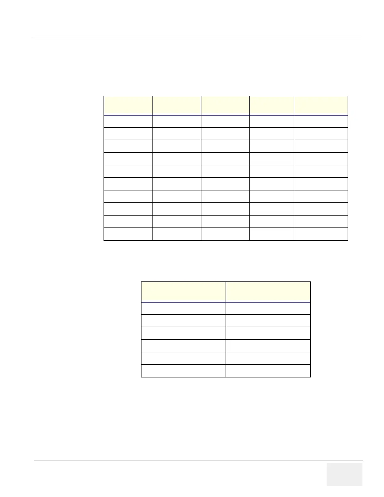
Table 4-11 Power Distributor Input and Output Voltages of LOGIQ™ 100 PRO .
Location for Testing HV on
FEB
Specification
FEB Test Point 90. 65 Vdc +/- 3Vdc.
FEB Test Point 91. 80 Vdc +/- 3 vdc.
FEB Test Point 62, 65 and 73. 12 Vdc +/- .3 vdc.
FEB Test Point 63, 67 and 70. 5 V dc +/- .3 vdc.
FEB Test Point 110. -12V dc +/- .3 vdc.
FEB Test Point 60 and 61. 3.3 V dc +/- .03 vdc.
Table 4-12 Voltage Test points on the FEB.
State: RELEASE - Document is released and under formal Change Control. Changes are subject to the ECR/ECO Process.
See the GEHC Myworkshop System to determine the status of this document.
Approved Document - 5305880-100TPH_r3.pdf Page 96 of 197
 Loading...


