EasyManua.ls Logo

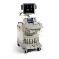
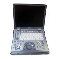
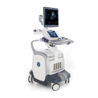
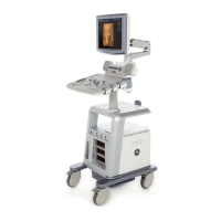
GE LOGIQ 100 PRO User Manual

GE LOGIQ 100 PRO
196 pages
To Next Page IconTo Next Page
Page #1 background imageLoading...
Page #1 background image
Technical
Publication
GE Healthcare
Direction 5305880-100
Revision 3
GE Healthcare
LOGIQ™ 100 PRO Service Manual
Copyrighted
©
1995-2008 by General Electric Co.
All Rights Reserved.
State: RELEASE - Document is released and under formal Change Control. Changes are subject to the ECR/ECO Process.
See the GEHC Myworkshop System to determine the status of this document.
Approved Document - 5305880-100TPH_r3.pdf Page 2 of 197

Table of Contents

Questions and Answers:

GE LOGIQ 100 PRO Specifications

General IconGeneral
Power Requirements100-240 VAC, 50/60 Hz
Display15" LCD
Probe TypesLinear, Convex, Phased array
B-ModeYes
M-ModeYes
Doppler ModesColor Doppler, Power Doppler

Summary

Chapter 1 Introduction

Section 1-2 Safety

Details critical safety precautions and warnings for operating and servicing the unit.

Section 1-4 Safety Considerations

Outlines essential safety precautions for operation, service, and repair.

Section 1-5 EMC, EMI, and ESD

Covers electromagnetic compatibility, interference, and electrostatic discharge.

Chapter 2 Pre Installation

Section 2-2 General Console Requirements

Details environmental and electrical requirements for console installation.

Chapter 3 Installation

Section 3-5 Completing the Installation

Details the steps for connecting transducers, power, and optional accessories.

Chapter 4 Functional Checks

Section 4-3 Functional Check Procedures

Details the steps for performing functional checks on the system.

Section 4-4 Diagnostics

Describes power-on and service diagnostics for the LOGIQ™ 100 PRO.

Section 4-7 Probe/Connectors Check

Provides steps to check probe connectivity and functionality.

Chapter 5 System Concepts

Section 5-3 Block Diagram

Presents block diagrams of the system and its main boards.

Section 5-5 Functional Subsystems

Details the functions of the Front End Board and Davinci Board.

Chapter 7 Diagnostics/Troubleshooting

Section 7-4 Troubleshooting

Provides a table to help service engineers with corrective maintenance.

Chapter 10 Quality Assurance

Section 10-6 Electrical Safety Tests

Covers safety test overview, leakage current limits, and outlet wiring tests.

Section 10-7 When There's Too Much Leakage Current...

Provides troubleshooting steps for chassis, probe, and peripheral fails.

Related product manuals