GE
D
IRECTION 5535208-100, REV. 2 LOGIQ E9 SERVICE MANUAL
Chapter 5 Components and Functions (Theory) 5 - 27
5-7-3 Power Up Sequence Description
5-7-3-1 Overview
The Power Up Sequence can be divided in the following steps:
1.) Switch AC Breaker to ON position
2.) Press the ON button on the Operator Panel
3.) BEP power-up
5-7-3-2 AC Breaker to ON position
1.) BEP, powered by 5Vstb, detects contact of Power-On Button.
2.) BEP sends PSON_N low to the Main Power supply.
3.) Main Power supply powers up +48V.
4.) Main Power supply powers up +24V, ±15V, ±6V, +11V.
5.) Main Power supply provides 48V_OK as soon as +48V is within specification.
6.) BEP Power supply Provides PC voltages from +48V.
7.) BEP enumerates PCI. (note that GFI DSP, or MRX DSP and PCI Express bridge must be powered
before BEP enumerates PCI).
8.) BEP application software controls +24V, ±15V, ±6V, +11V via USB (RackPower 0x6A).
9.) BEP application software controls TSV1and TSV2 via USB (SetTxPS 0x68).
10.)Main Power supply provides TS_OK and TS_LEVEL_OK output signals to GFI or MRX.
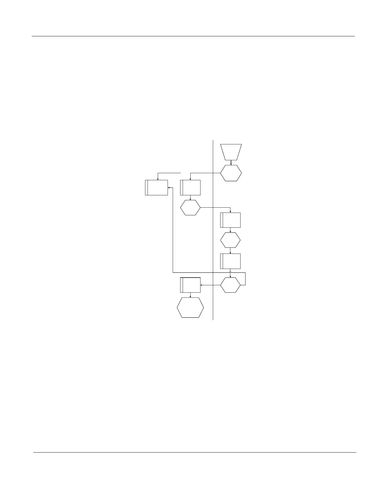
Figure 5-17 Power On Sequence
Op I/O
Power On
PSON_N
via BEP
(5Vstb)
M
a
n
+48V
48V_OK
BEP
PS-OK
BEP
enumerates PCI
TS Voltage
M
a
n
PC Voltages
TS_OK
TS_LEVEL_OK
USB
BEP
M
a
i
+24V
+/-15, +/-6, +11V
PSON_N