GE
D
IRECTION 5535208-100, REV. 2 LOGIQ E9 SERVICE MANUAL
Chapter 8 Replacement procedures 8 - 45
8-5-7 Front Cover replacement
8-5-7-1 Front Cover removal
The Front Cover Assembly is made of two pieces.
Table 8-25 Manpower / Time and Tools
Manpower /
Time
Tools
One person /
15 minutes
Refer to: 8-2-5 "Tools needed for servicing the LOGIQ E9" on page 8-5.
Table 8-26 Preparations and Preparation Links
Preparations - you must perform the following steps
1. Power down the system.
2. Disconnect the mains power cable from the wall outlet and all Probes and External I/O Cabling.
3. Remove the Side Covers, Top Cover and the Foot Rest Bumper.
Preparation Links (if you need more information):
• 4-2-3 "Power shut down" on page 4-7.
• 8-5-2 "Side Covers replacement" on page 8-30.
• 8-5-4 "Top Cover replacement" on page 8-38.
• 8-5-6 "Foot Rest Bumper replacement" on page 8-43.
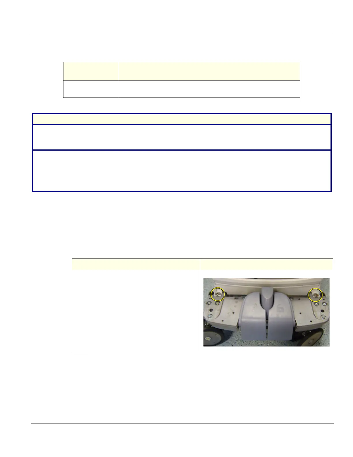
Table 8-27 Front Cover Screw placement
Steps
Corresponding Graphic
1.. Unscrew the two Phillips screws that fix the
Front Cover Assembly to the chassis.
Pull the upper end of the Front Cover out
and upwards to free it from the pedals and
the frame.