EasyManuals Logo

GE LOGIQ E9 Service Manual

GE LOGIQ E9
808 pages
To Next Page IconTo Next Page
To Previous Page IconTo Previous Page
Page #392 background imageLoading...
Page #392 background image
GE
D
IRECTION 5535208-100, REV. 2 LOGIQ E9 SERVICE MANUAL
8 - 46 Section 8-5 - Replacing Covers and Bumpers
8-5-7-2 Front Cover installation
Table 8-28 Front Cover installation
Steps
Corresponding Graphic
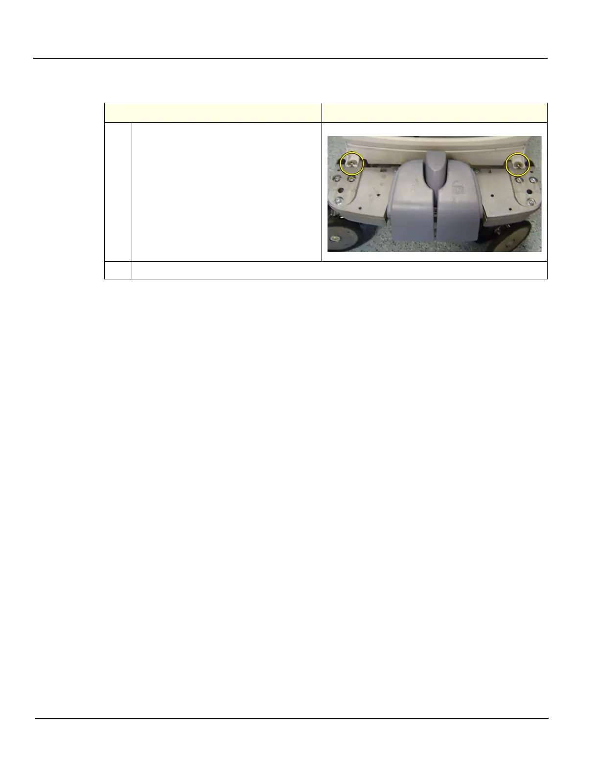
1. Thread the Front Cover so it fits in between
chassis and pedals.
Align the Front Cover guide pins with holes
in the frame.
Front Cover Assembly (cover on left and
probe plate on right) with guide pins.
Fasten Front Cover with two Phillips
screws.
2. Install the Foot Rest Bumper, the Top Cover and the Side Covers.

Table of Contents

Other manuals for GE LOGIQ E9

Questions and Answers:

Question and Answer IconNeed help?

Do you have a question about the GE LOGIQ E9 and is the answer not in the manual?

GE LOGIQ E9 Specifications

General IconGeneral
TypeUltrasound System
3D/4D ImagingYes
Transducer Ports4 active ports
ConnectivityDICOM, USB, Ethernet
ApplicationsAbdominal, Vascular, Musculoskeletal, Small Parts, Urology, Pediatric, Cardiac, Obstetrics/Gynecology
TransducersLinear, Convex, Phased Array, Volume
Doppler ModesColor Doppler, Power Doppler, Pulsed Wave Doppler, Continuous Wave Doppler
ElastographyYes
Advanced FeaturesB-Flow, Volume Navigation
PortabilityCart-based system
Display19-inch high-resolution LCD monitor

Related product manuals