GE
D
IRECTION 5535208-100, REV. 2 LOGIQ E9 SERVICE MANUAL
Chapter 8 Replacement procedures 8 - 113
8-6-3-3 LCD Monitor V2 Arm assembly replacement - R5.x and later (cont’d)
Table 8-70 LCD Monitor V2 Arm assembly installation - R5 and later
Steps Corresponding Graphic
1.
WHEN INSTALLING THE LCD ARM ASSEMBLY, KEEP THE LCD ARM IN THE LOCKED
POSITION. THE SPRINGS TO SUPPORT THE LCD CAN CAUSE THE ARM TO SPRING
OPEN CAUSING SEVERE PERSONAL INJURY AND PROPERTY DAMAGE.
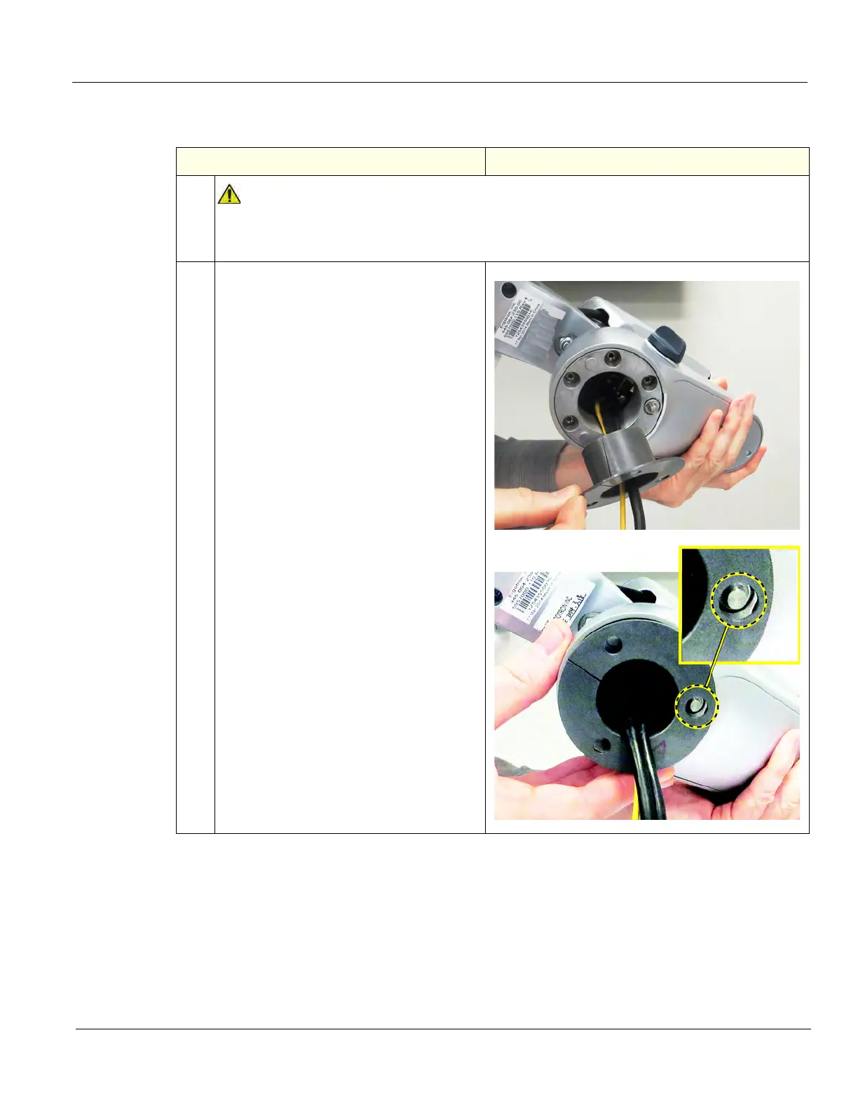
2.
Make sure the Bushing is installed and
positioned in the orientation shown. The
larger hole in the Bushing is to
accommodate the pin.