GE
D
IRECTION 5535208-100, REV. 2 LOGIQ E9 SERVICE MANUAL
8 - 114 Section 8-6 - Replacing Top Console Parts
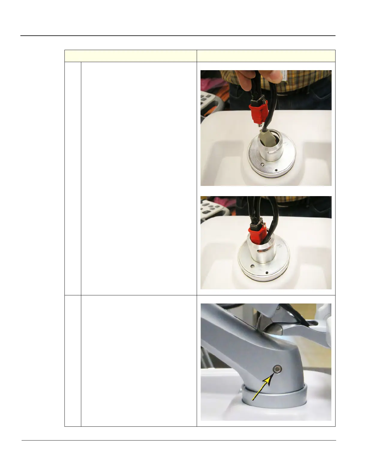
3.
The R5 and later Arm Assembly Cable
route in the same manner as R4, except
there is now a ground Cable for the Arm.
Take the LCD Arm and Cables and feed the
LCD Power Cable into the Adapter first.
Position the Video Cable Connector as
shown and continue to feed the cables into
the Adapter.
Install the Arm Assembly.
4.
Position the Arm Assembly so the Set
Screw mounting hole faces the left side of
the LOGIQ E9.
Install the Set Screw. Torque: 9.8 Nm
(7.2 lbf-ft {86.4 lbf-in}).
Table 8-70 LCD Monitor V2 Arm assembly installation - R5 and later
Steps Corresponding Graphic