GE
D
IRECTION 5535208-100, REV. 2 LOGIQ E9 SERVICE MANUAL
8 - 122 Section 8-6 - Replacing Top Console Parts
8-6-4-3 Calibration and adjustments
Refer to: Section 6-3 "LCD Monitor adjustments" on page 6-2 for LCD Monitor calibration instructions.
8-6-4-4 Verification
Perform the following steps to verify that the product is functioning as intended after this replacement:
1.) Verify that all screws that you removed earlier have been installed.
2.) If finished, connect cables and Probes removed earlier.
3.) Power up the LOGIQ E9 to verify that it operates as intended.
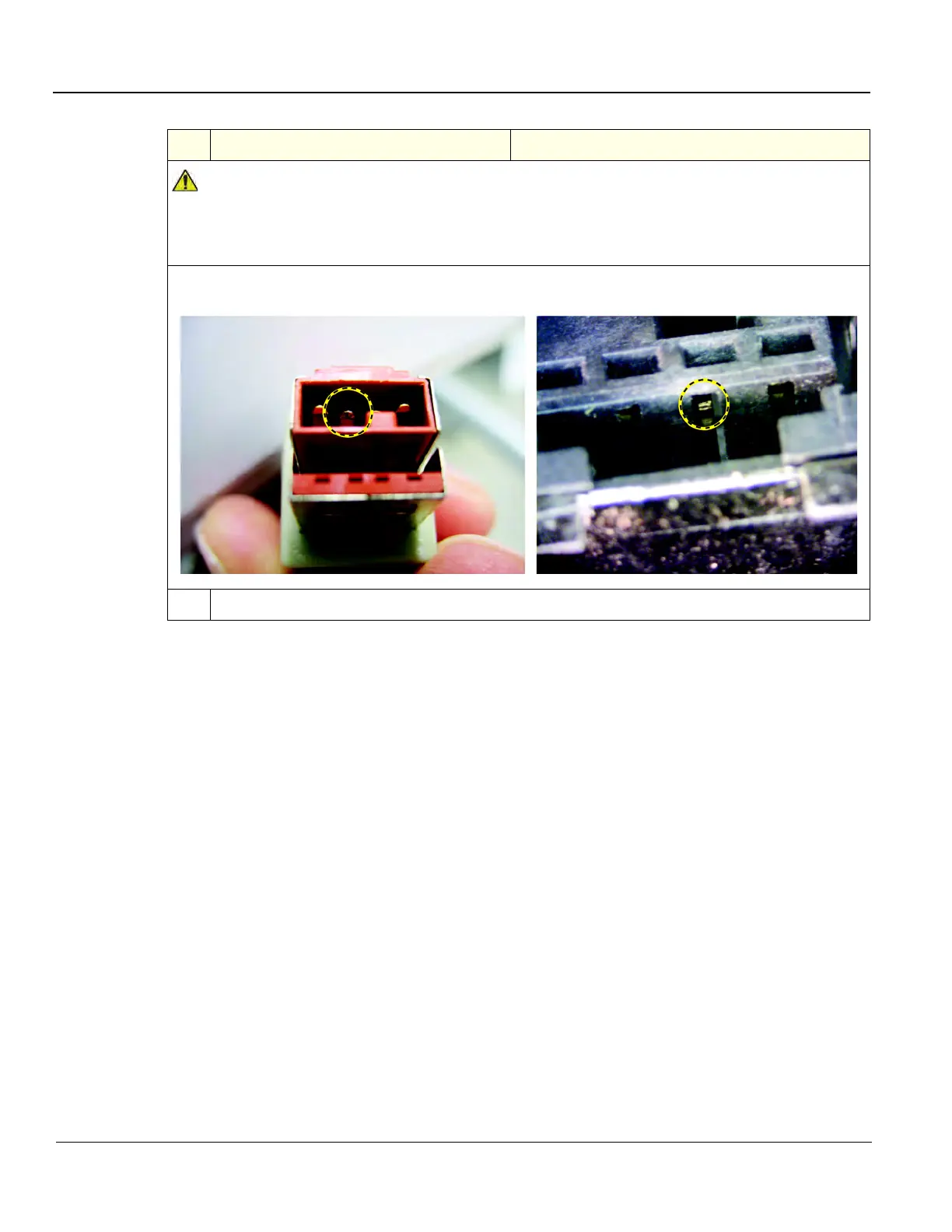
DO NOT connect the LCD power cable to the power (P3) connector on the Bulkhead when the
LOGIQ E9 is powered up. Damage to the LCD Power Cable and/or the Bulkhead Board can
occur. See: images below of damage that can occur.
48VDC pin in the P3 connector (center pin), shows damage.
The outside two pins are Ground. Cable left, Bulkhead Connector right.
5.
Install the Bulkhead Cover.
Table 8-75 V2 Arm Adapter installation
Steps Corresponding Graphic