GE
D
IRECTION 5535208-100, REV. 2 LOGIQ E9 SERVICE MANUAL
Chapter 8 Replacement procedures 8 - 131
8-6-8 Upper Operator Panel / Touch Panel Assembly replacement
8-6-8-1 Upper OP Panel/Touch Panel Assembly removal
Table 8-87 Upper OP Panel/Touch Panel Assembly removal
Steps Corresponding Graphic
1. Make sure that the OP Panel is in its
uppermost position, with the LCD out of the
way:
OP Panel/Touch Panel Assembly
2. Remove the five OP Panel Knobs.
Failure to remove the five OP Panel Knobs first, could cause damage to the knob shafts.
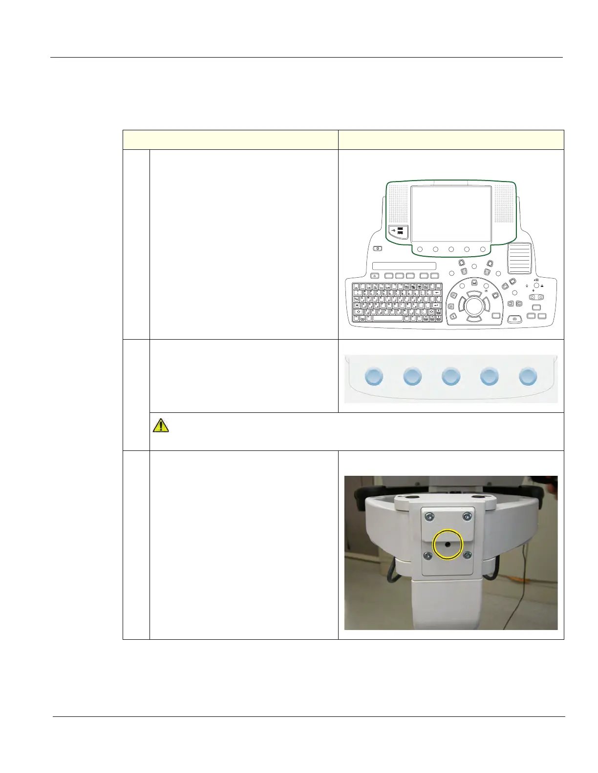
3. At the rear of the system, release the
frogleg mechanism for the console by
inserting a screwdriver into the release
point and pressing until release. Pull the
console out to its extended position to gain
access to the screws in the next step.
XY / Frogleg mechanism release
Depth
Steer Width
R
L
P
3D/4D
Measure
Comment
Clear
Zoom
H
D
n
r
N
l
o
i
i
w
Freeze
LOGIQ
1
2