EasyManuals Logo

GE LOGIQ E9 Service Manual

GE LOGIQ E9
808 pages
To Next Page IconTo Next Page
To Previous Page IconTo Previous Page
Page #560 background imageLoading...
Page #560 background image
GE
D
IRECTION 5535208-100, REV. 2 LOGIQ E9 SERVICE MANUAL
8 - 214 Section 8-9 - BEP (Back End Processor) parts replacement
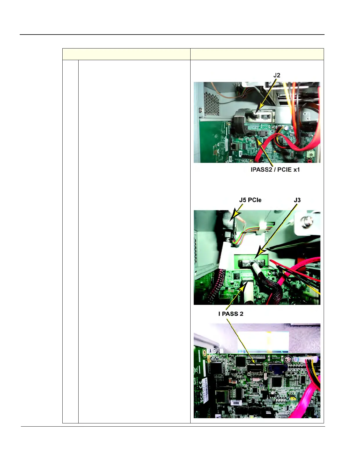
5. Reach inside the BEP and connect the
BEP cable to the Backplane J2 (left) on a
MRX Configuration.
MAKE sure the BEP Cable to the
Backplane for BEP6 is installed as shown.
DO NOT twist.
Or, the Backplane cable, J3 (right) and J5
PCIe to the Card Rack on a GFI
Configuration, using a BEP6.
BEP Cable to MRX Backplane, J2
BEP Cable to Backplane J3 of GFI Configuration
(view inside the BEP)
Table 8-127 BEP installation
Steps Corresponding Graphic

Table of Contents

Other manuals for GE LOGIQ E9

Questions and Answers:

Question and Answer IconNeed help?

Do you have a question about the GE LOGIQ E9 and is the answer not in the manual?

GE LOGIQ E9 Specifications

General IconGeneral
TypeUltrasound System
3D/4D ImagingYes
Transducer Ports4 active ports
ConnectivityDICOM, USB, Ethernet
ApplicationsAbdominal, Vascular, Musculoskeletal, Small Parts, Urology, Pediatric, Cardiac, Obstetrics/Gynecology
TransducersLinear, Convex, Phased Array, Volume
Doppler ModesColor Doppler, Power Doppler, Pulsed Wave Doppler, Continuous Wave Doppler
ElastographyYes
Advanced FeaturesB-Flow, Volume Navigation
PortabilityCart-based system
Display19-inch high-resolution LCD monitor

Related product manuals