EasyManuals Logo

GE LOGIQ E9 Service Manual

GE LOGIQ E9
808 pages
To Next Page IconTo Next Page
To Previous Page IconTo Previous Page
Page #568 background imageLoading...
Page #568 background image
GE
D
IRECTION 5535208-100, REV. 2 LOGIQ E9 SERVICE MANUAL
8 - 222 Section 8-9 - BEP (Back End Processor) parts replacement
8-9-5-1 BEP Side I/O Board removal
Table 8-135 BEP Side I/O Board removal
Steps Corresponding Graphic
1.
Disconnect all I/O cables and all cables at the top of the BEP.
2.
Loosen the thumb screws or screws at the top of the BEP cover, or the three screws that attach
the cover to the BEP.
Tilt the top of the BEP cover away from the BEP.
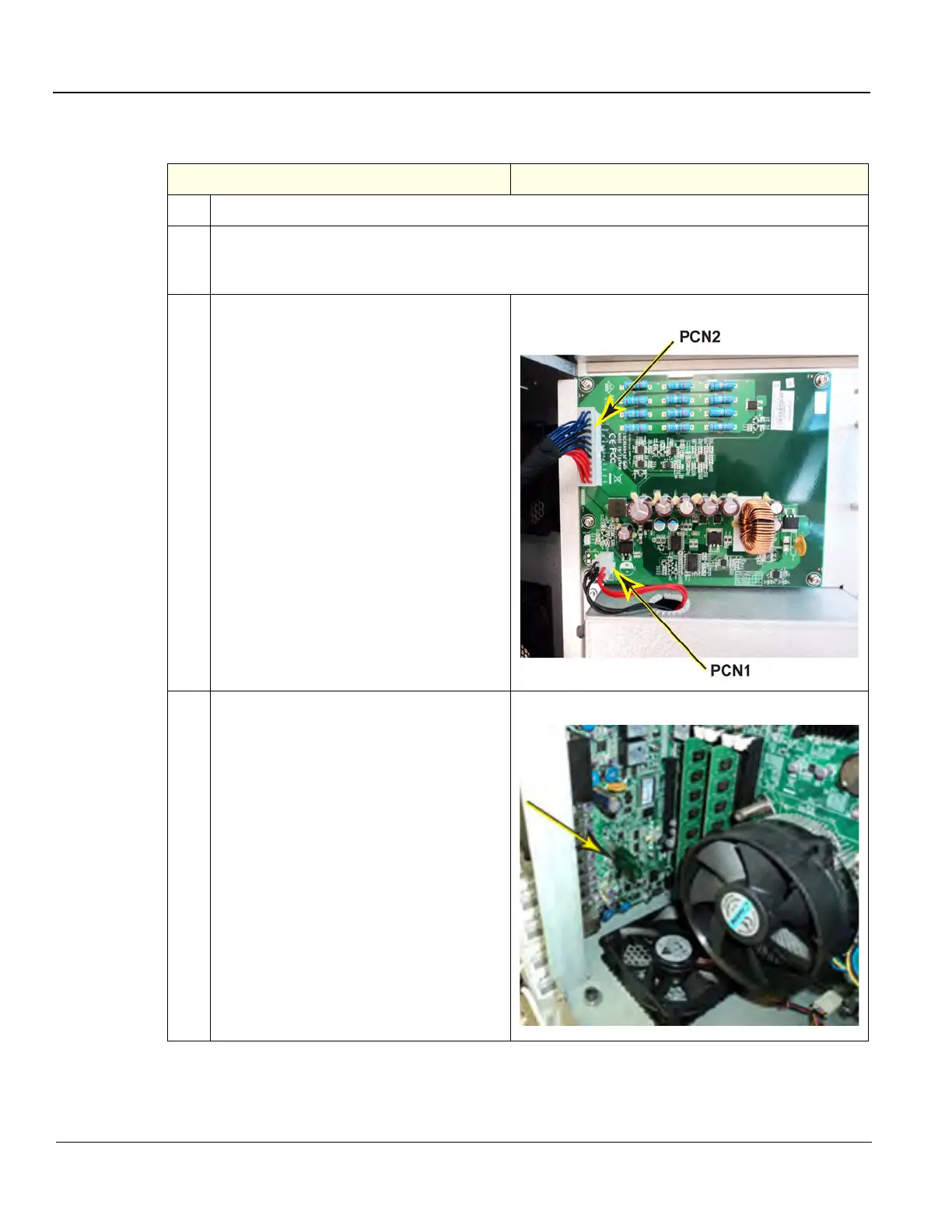
3.
Disconnect:
• the battery cable from PCN1.
• the CB to PB cable from PCN2.
Place the BEP cover aside.
BEP6 CB cables
4.
Remove the Option Dongle, on the I/O
Board, inside the BEP.
Option Dongle

Table of Contents

Other manuals for GE LOGIQ E9

Questions and Answers:

Question and Answer IconNeed help?

Do you have a question about the GE LOGIQ E9 and is the answer not in the manual?

GE LOGIQ E9 Specifications

General IconGeneral
TypeUltrasound System
3D/4D ImagingYes
Transducer Ports4 active ports
ConnectivityDICOM, USB, Ethernet
ApplicationsAbdominal, Vascular, Musculoskeletal, Small Parts, Urology, Pediatric, Cardiac, Obstetrics/Gynecology
TransducersLinear, Convex, Phased Array, Volume
Doppler ModesColor Doppler, Power Doppler, Pulsed Wave Doppler, Continuous Wave Doppler
ElastographyYes
Advanced FeaturesB-Flow, Volume Navigation
PortabilityCart-based system
Display19-inch high-resolution LCD monitor

Related product manuals