EasyManuals Logo

GE LOGIQ E9 Service Manual

GE LOGIQ E9
808 pages
To Next Page IconTo Next Page
To Previous Page IconTo Previous Page
Page #569 background imageLoading...
Page #569 background image
GE
D
IRECTION 5535208-100, REV. 2 LOGIQ E9 SERVICE MANUAL
Chapter 8 Replacement procedures 8 - 223
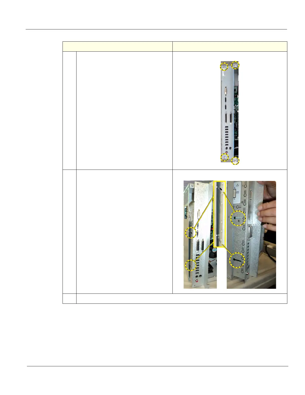
5.
Remove the four Phillips screws securing
the Side I/O Board to the BEP frame.
6.
Slowly and carefully pull the I/O Board out
of the BEP, making sure to avoid hitting
components and circuit pins on both sides
of the Board. Pay attention to the
installation guide pins and the slots in the
bracket that need to be clear as I/O Board
and bracket are removed.
I/O Board installation guides and slots
7.
Set the I/O Board aside.
Table 8-135 BEP Side I/O Board removal
Steps Corresponding Graphic

Table of Contents

Other manuals for GE LOGIQ E9

Questions and Answers:

Question and Answer IconNeed help?

Do you have a question about the GE LOGIQ E9 and is the answer not in the manual?

GE LOGIQ E9 Specifications

General IconGeneral
TypeUltrasound System
3D/4D ImagingYes
Transducer Ports4 active ports
ConnectivityDICOM, USB, Ethernet
ApplicationsAbdominal, Vascular, Musculoskeletal, Small Parts, Urology, Pediatric, Cardiac, Obstetrics/Gynecology
TransducersLinear, Convex, Phased Array, Volume
Doppler ModesColor Doppler, Power Doppler, Pulsed Wave Doppler, Continuous Wave Doppler
ElastographyYes
Advanced FeaturesB-Flow, Volume Navigation
PortabilityCart-based system
Display19-inch high-resolution LCD monitor

Related product manuals