GE
D
IRECTION 5535208-100, REV. 2 LOGIQ E9 SERVICE MANUAL
Chapter 8 Replacement procedures 8 - 267
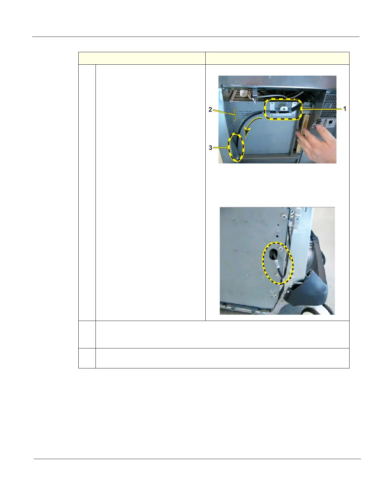
6.
Check that the GFI PCIe Cable is
behind the Main PS fang (1). GFI
Configuration only. MRX does not use
this cable.
Put the Main PS into position so it will
be ready to be mounted.
Feed the USB cable from the Main PS,
between the BEP and the Targa frame
and then feed the USB cable through
the gap prior to fastening the Main PS
to the Targa frame.
Check that the GFI PCIe cable
between the rear of the Card Cage (2)
and the Targa frame (3).
NOTE: If applicable; only on GFI Card
Rack configuration.
Side view of the PCIe Cable routed
between the Card Cage and Targa.
GFI Configuration only. MRX does not
use this cable.
7.
Install the Rear Cover and Side Covers.
Record VPD information for 4D Motor Controller. For information on updating VPD, see:
8-4-7-2 "Verify and Update Vital Product Data" on page 8-28.
8.
Perform Functional Checks. See: 8-10-4-5 - Calibration and adjustments,
8-10-4-6 - Verification and 8-10-4-7 "Functional Checks" on page 8-268.
Table 8-168 4D MC Reinstallation for Lambda PS
Steps Corresponding Graphic