CHAPTER 5: SETTINGS GROUPED ELEMENTS
M60 MOTOR PROTECTION SYSTEM – INSTRUCTION MANUAL 5-213
5
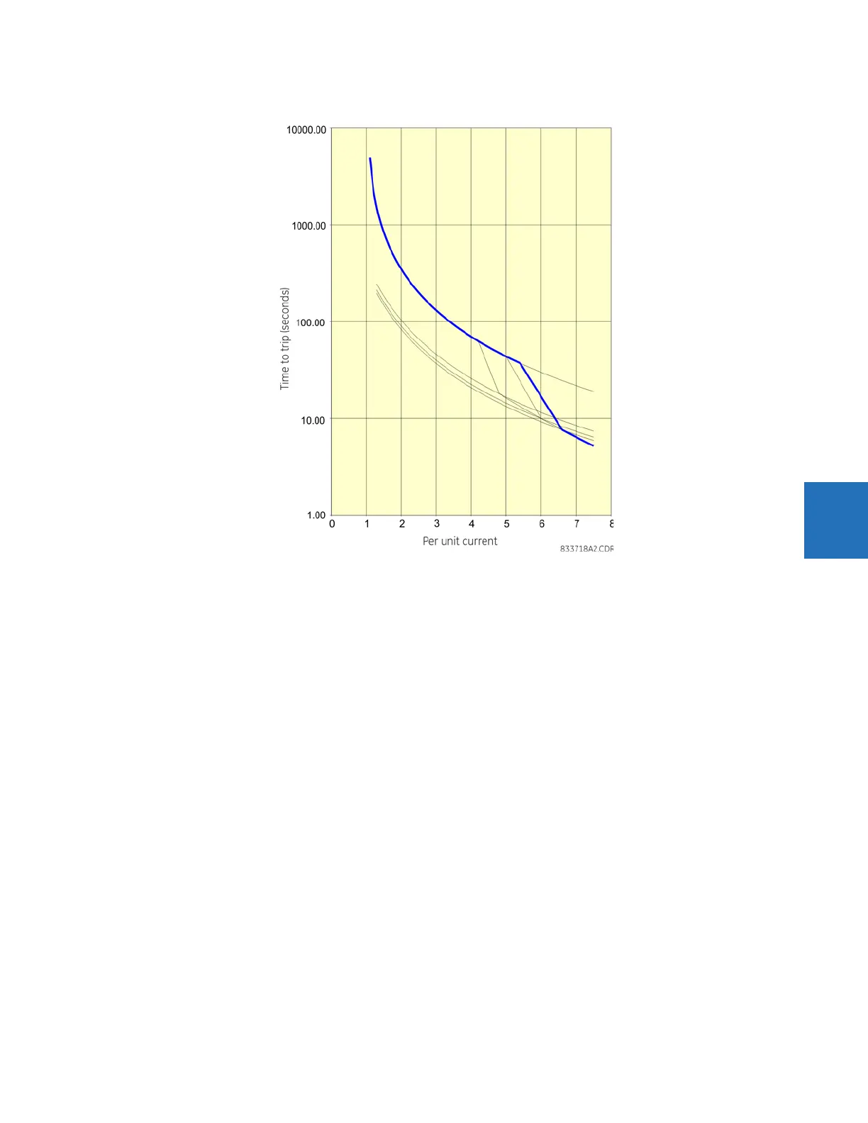
Figure 5-111: Voltage dependent overload curve protection at 110% voltage
The following three figures illustrate the motor starting curves for the following abnormal conditions: line voltages below
the minimum, above 110%, and the situation for voltage loss.