94 MDS 4790/9790 Series I/O Guide MDS 05-3438A01, Rev. F
2. Open the radio chassis, locate the TX cable, and disconnect the
cable from vertical interface board.
3. Using an adapter, connect the RF power meter to the SMA connec-
tor on the vertical interface board, key the radio and measure the RF
power.
If the power registers +39 dBm, the radio board is functioning
correctly.
If the power registers less than +39 dBm, proceed with Step 4.
4. Use the front panel to switch to the alternate transmitter and again
measure the RF power output.
If the alternate transmitter registers +39 dBm, the antenna switch
probably requires replacement.
5. Before replacing the antenna switch, make sure that +14 Vdc is
present on Pin 2 of J14 and Pin 1 is less than 1 Vdc on the PCB
interface.
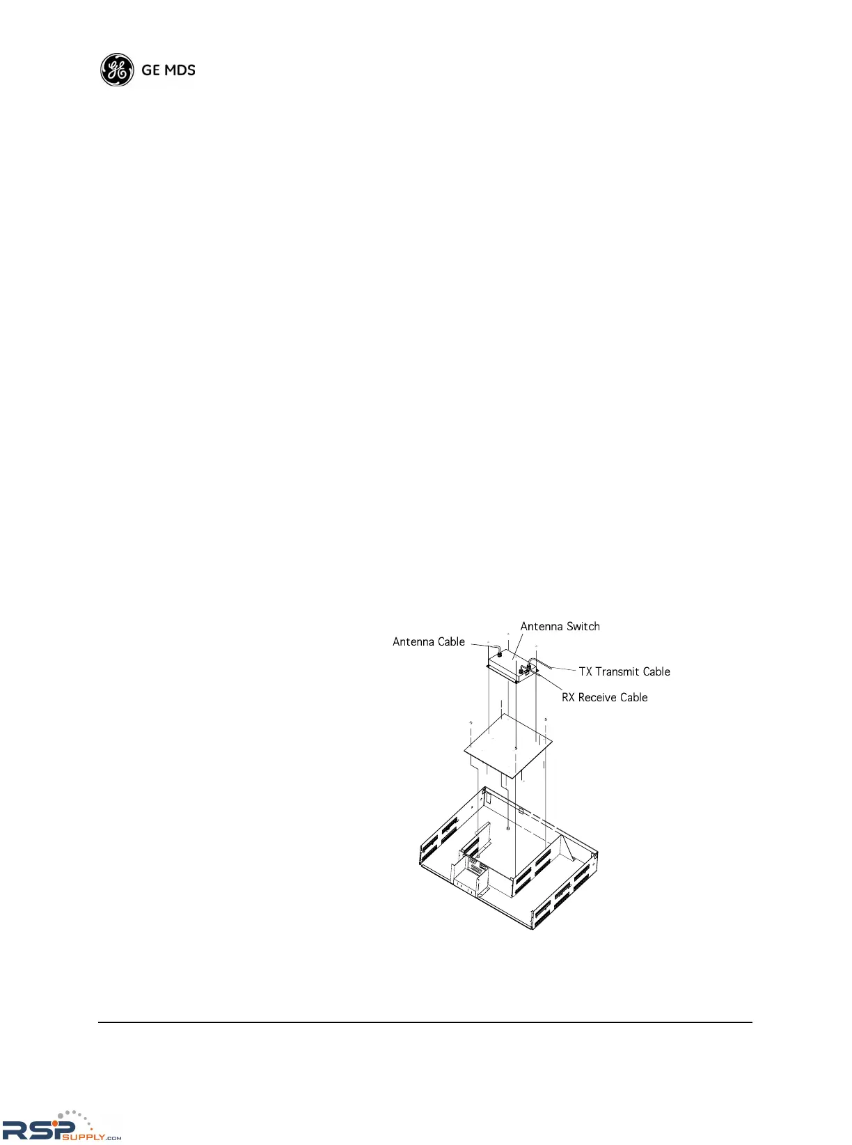
Removing the Antenna Switch
To remove the antenna switch module:
1. Remove the four screws that mount the antenna switch module to
the chassis as shown in Figure 47.
2. Disconnect the cables from the switch module and lift the module
out of the chassis.
Figure 47. Antenna Switch Module Removal
 Loading...
