MDS 05-3438A01, Rev. F MDS 4790/9790 Series I/O Guide 23
Data Interface Connector—J3
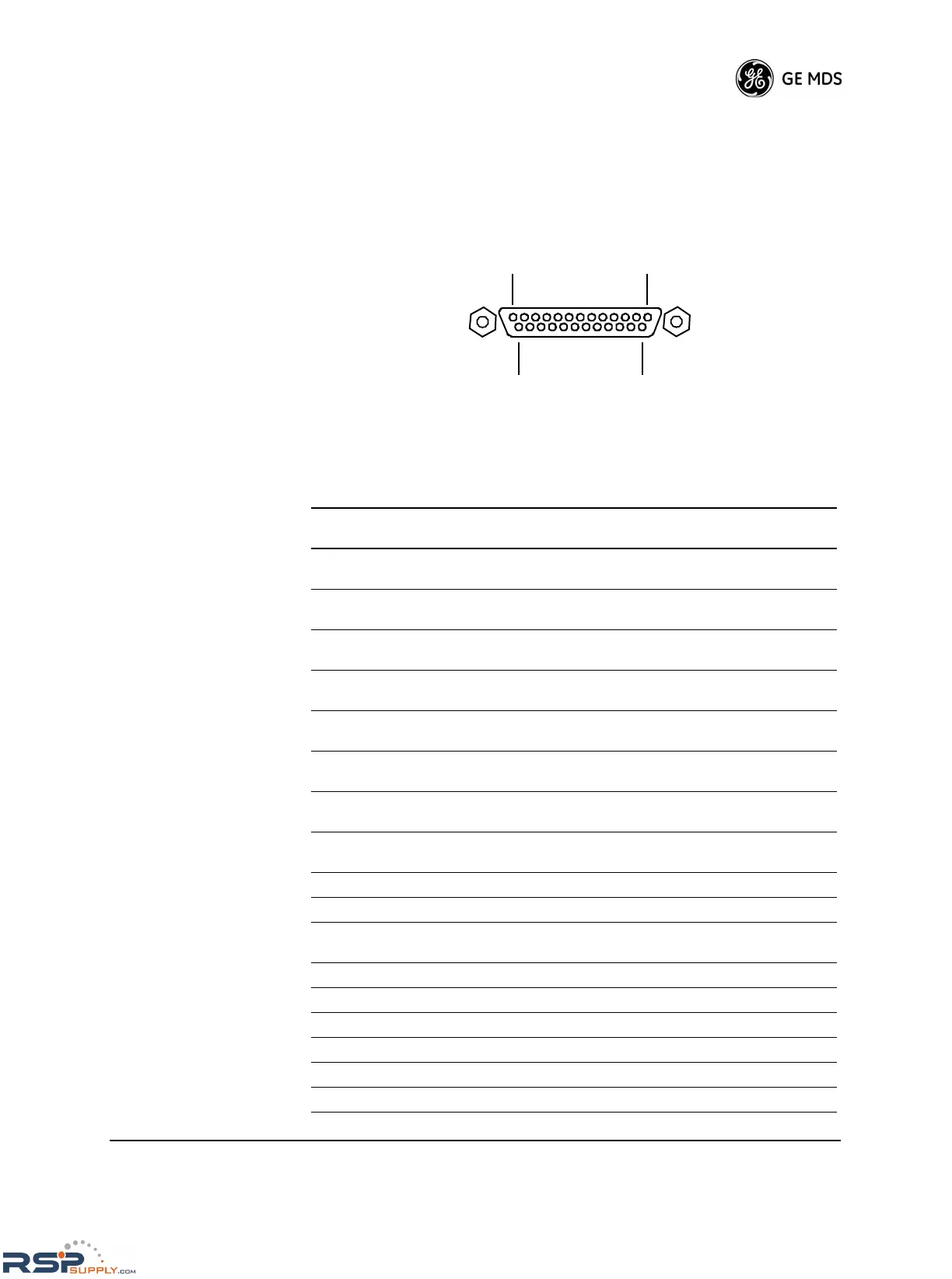
The data connector on the radio’s rear panel is the main system data
interface. It typically connects to the host computer. Refer to Figure 21
and Table 5 on Page 23 for pinout details. Refer to Figure 22 on Page 24
for information on connecting the radio to a VOX assembly.
Invisible place holder
Figure 21. Data Interface Connector, J3
Table 5. Data Interface Pinout
Pin
Number
Input/Output Pin Description
1— Shield Connection. Connects to ground (negative
supply potential) on the radio’s PC board.
2IN TXD—Transmitted Data. Accepts TX data from the
connected device.
3OUT RXD—Received Data. Sends received data to the
connected device.
4IN RTS—Request-to-Send Input. Keys the
transmitter when RTS is asserted.
5OUT CTS—Clear-to-Send Output. Active after the
programmed CTS delay time has elapsed.
6OUT DSR—Data Set Ready. Provides a +6 Vdc DSR
signal through a 2.5 kΩ resistor.
7-- Signal Ground. Connects to ground (negative
supply potential) at the radio’s PC board.
8OUT DCD—Data Carrier Detect. Activates when the
radio detects an on-frequency signal.
9 -- No Connection
10 -- No Connection
11 OUT Receive Audio Monitoring Connection (used for
diagnostics). Drives high-impedance load.
12 -- No Connection
13 -- No Connection
14 -- No Connection
15 OUT Do not connect—Reserved for future use.
16 -- No Connection
17 -- Do not connect—Reserved for future use.
 Loading...
