22 MDS 4790/9790 Series I/O Guide MDS 05-3438A01, Rev. F
Invisible place holder
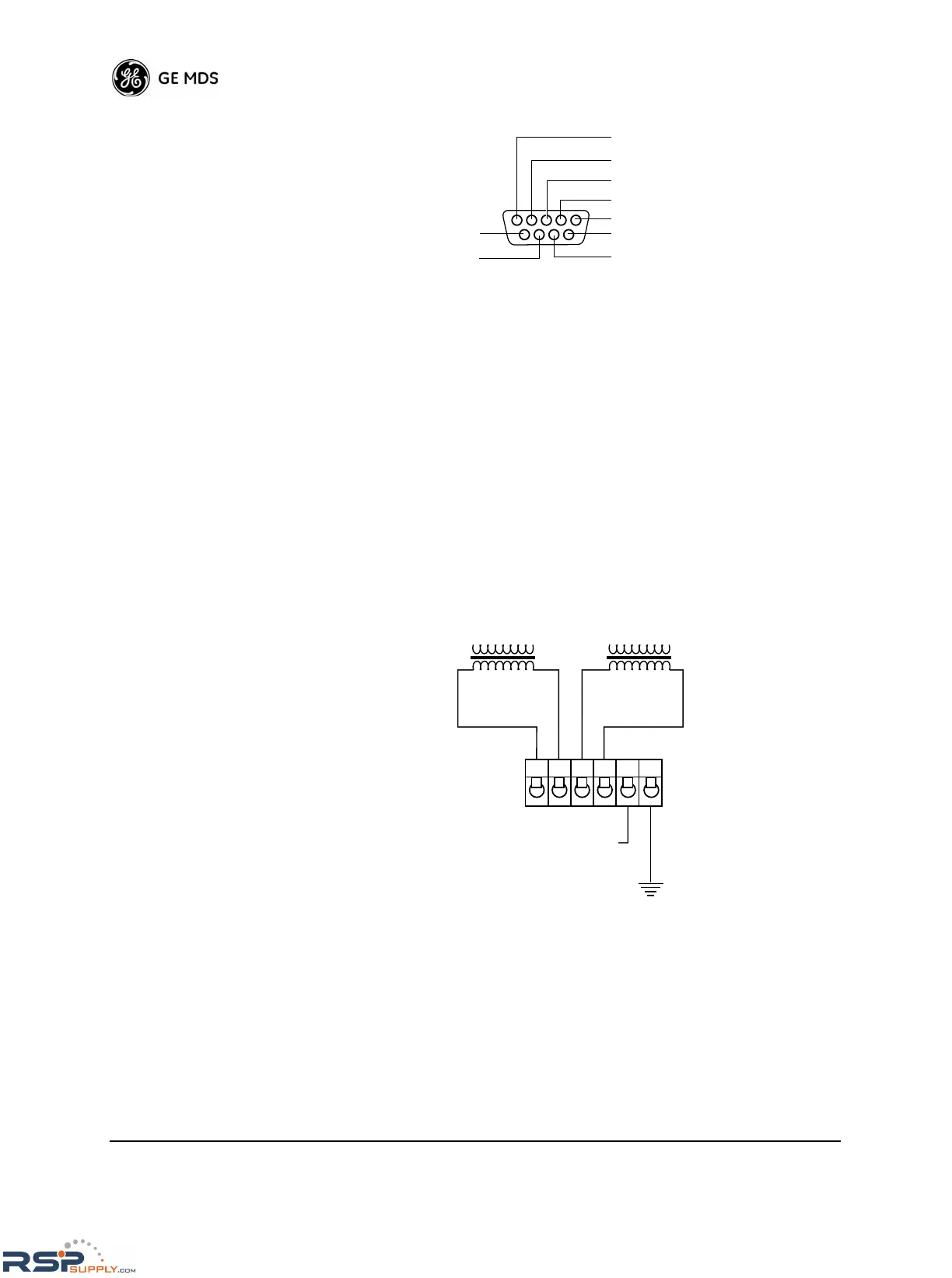
Figure 19. Diagnostics Port Connector, J1
4-Wire Audio Connector—J2
J2 is a plug-in terminal strip that provides connections for 4-wire audio
circuits. Figure 20 shows the function of each terminal as viewed from
the rear panel.
Terminals 1 and 2 are for transmit audio input with a nominal 600 Ω
impedance. Terminals 3 and 4 provide a receive audio output with a
nominal 600 Ω impedance. Pins 5 and 6 provide an external keying
source. Shorting pins 5 and 6 keys the radio.
Refer to Figure 22 on Page 24 for information on connecting the radio
to a VOX assembly.
Figure 20. 4-Wire Audio Connector, J2
PIN 2— RXD
PIN 3— TXD
PIN 4— +5 Vdc
PIN 5— GROUND
PIN 7— RTS*
* Used when reprogramming the radio firmware with a PC
 Loading...
