24 MDS 4790/9790 Series I/O Guide MDS 05-3438A01, Rev. F
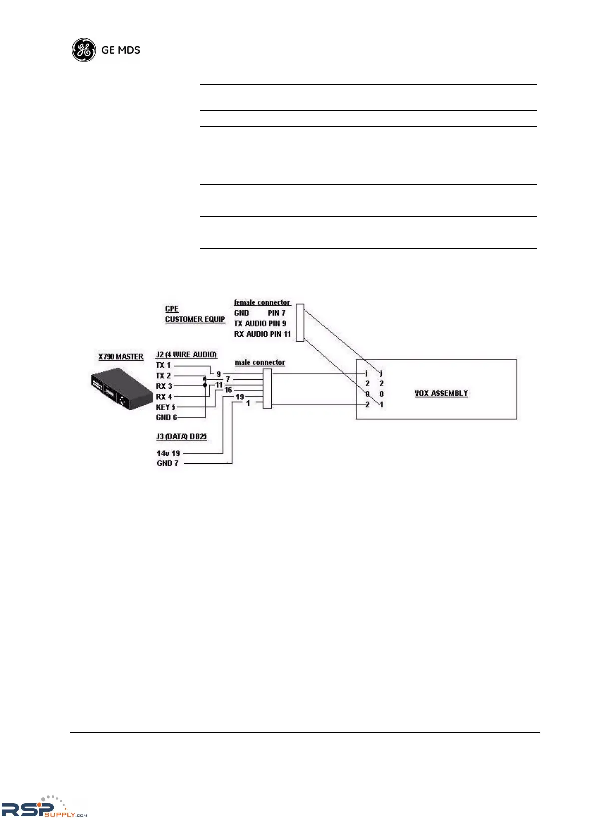
Figure 22. x790 to VOX Assembly Interconnect Diagram
Orderwire Connector—J9
The radio provides for an orderwire channel to facilitate communica-
tions between two associated MDS 4790/9790 radios. The jack accepts
a standard telephone handset with a carbon microphone and an RJ-11
connector-equipped cable. See “Coordinating Activities by Orderwire”
on Page 27 for more information.
Alarm Contacts—J10
J10 is a plug-in terminal strip that provides connections for optional
alarm circuits. Figure 23 shows the function of each terminal as viewed
from the rear panel.
18 -- No Connection
19 OUT 14.0 Vdc Output. Provides a regulated supply
voltage at 1.5 A for low-power accessories.
20 -- No Connection
21 -- No Connection
22 -- No Connection
23 -- No Connection
24 -- Do not connect—Reserved for future use.
25 -- No Connection
Table 5. Data Interface Pinout (Continued)
Pin
Number
Input/Output Pin Description
 Loading...
