QUICK START GUIDE
1. Install and connect the antenna system to the radio (page 9).
• Use an appropriate antenna aimed at the associated station.
• Use low-loss feedline suited for 400/900 MHz. Keep the feedline as short as possible.
2. Connect the backup battery (page 15).
3. Connect the host computer to the DATA connector on the rear panel (page 23).
4. Verify proper input voltage level and connect power to the radio.
Set the power switch(es) to ON.
5. Configure the data interface baud rate (page 42).
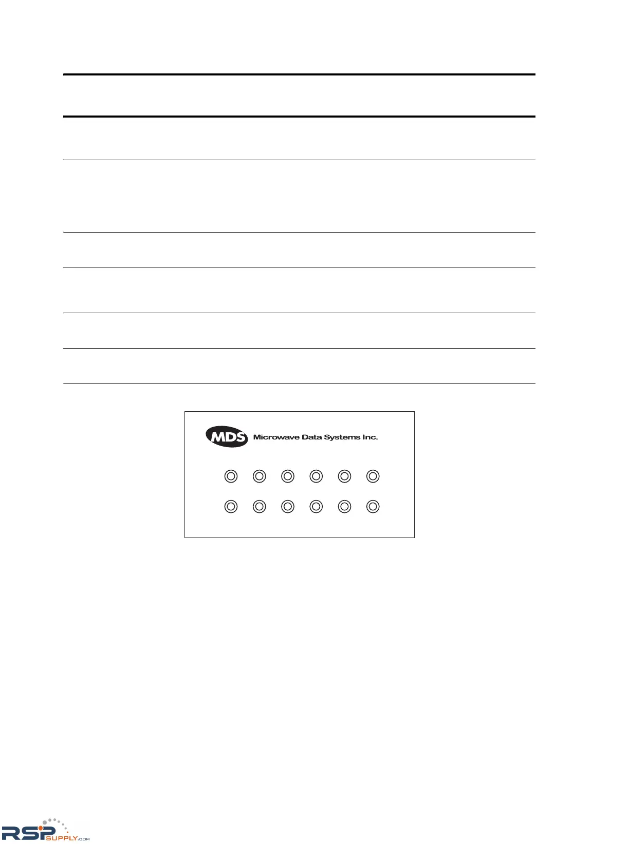
6. Observe front panel indicators for proper operation.
Invisible place holder
ACTIVE (green)—This transceiver board (A or B) is the selected unit.
STBY (yellow)—This transceiver board (A or B) is the standby unit (redundant version only).
ALARM (red)—General fault not covered by the other alarm categories (RX ALR, TX ALR, I/O ALR).
RX ALR (red)—Difficulty receiving. May be due to an antenna problem, receiver fault, or other
condition causing a low received signal level.
TX ALR (red)—Fault with the transmit circuitry.
I/O ALR (red)—The data rate or format of data at the data interface connector is incompatible with the
radio settings.
A
B
ACTIVE STBY ALARM RX ALR TX ALR I/O ALR
ACTIVE STBY ALARM RX ALR TX ALR I/O ALR
 Loading...
