MDS 05-3438A01, Rev. F MDS 4790/9790 Series I/O Guide 85
4. Use the DLINK ON and DLINK [baud rate] commands to
enable network-wide diagnostics and set the baud rate at the DIAG-
NOSTICS
port of each node radio.
5. Connect same-site radios using a null-modem cable at the radios’
DIAGNOSTICS ports.
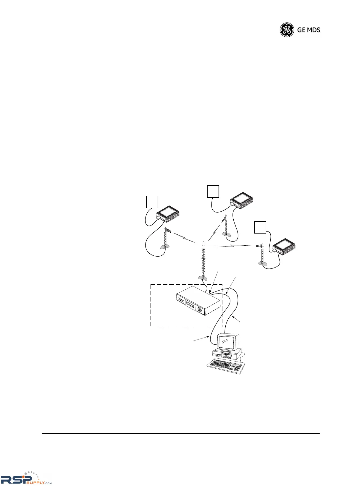
6. Connect a PC on which MDS InSite software is installed to the root
radio, or to one of the nodes, at the radio’s DIAGNOSTICS port (this
PC can be the PC that collects payload data, as shown in Figure 37).
To connect a PC to the radio’s DIAGNOSTICS port, an RJ-11 to
DB-9 adapter (MDS P/N 03-3246A01) is required. If desired, you
can construct an adapter cable from scratch using the information
shown in Figure 38 on Page 86.
7. Launch the MDS InSite software at the PC. See the InSite Radio
System Management Software User’s Guide for instructions.
Invisible place holder
Figure 37. Network-Wide Remote Diagnostics Setup
RTU
RTU
TO
DIAGNOSTICS
PORT
TO DATA
PORT
MASTER STATION
ROOT
DTYPE
ROOT
DIAGNOSTICS DATA
(TO InSite)
HOST COMPUTER
PAYLOAD DATA
RTU
(TO SCADA APPLICATION)
DTYPE
NODE
DTYPE
NODE
DTYPE
NODE
 Loading...
