CHAPTER 3: INSTALLATION INSTALLATION
MULTILINK ML3000 ETHERNET COMMUNICATIONS SWITCH – INSTRUCTION MANUAL 3–7
3.4 Electrical Installation
3.4.1 Powering the ML3000
Units with the AC power supply option can be connected directly to 110/240 V AC outlet.
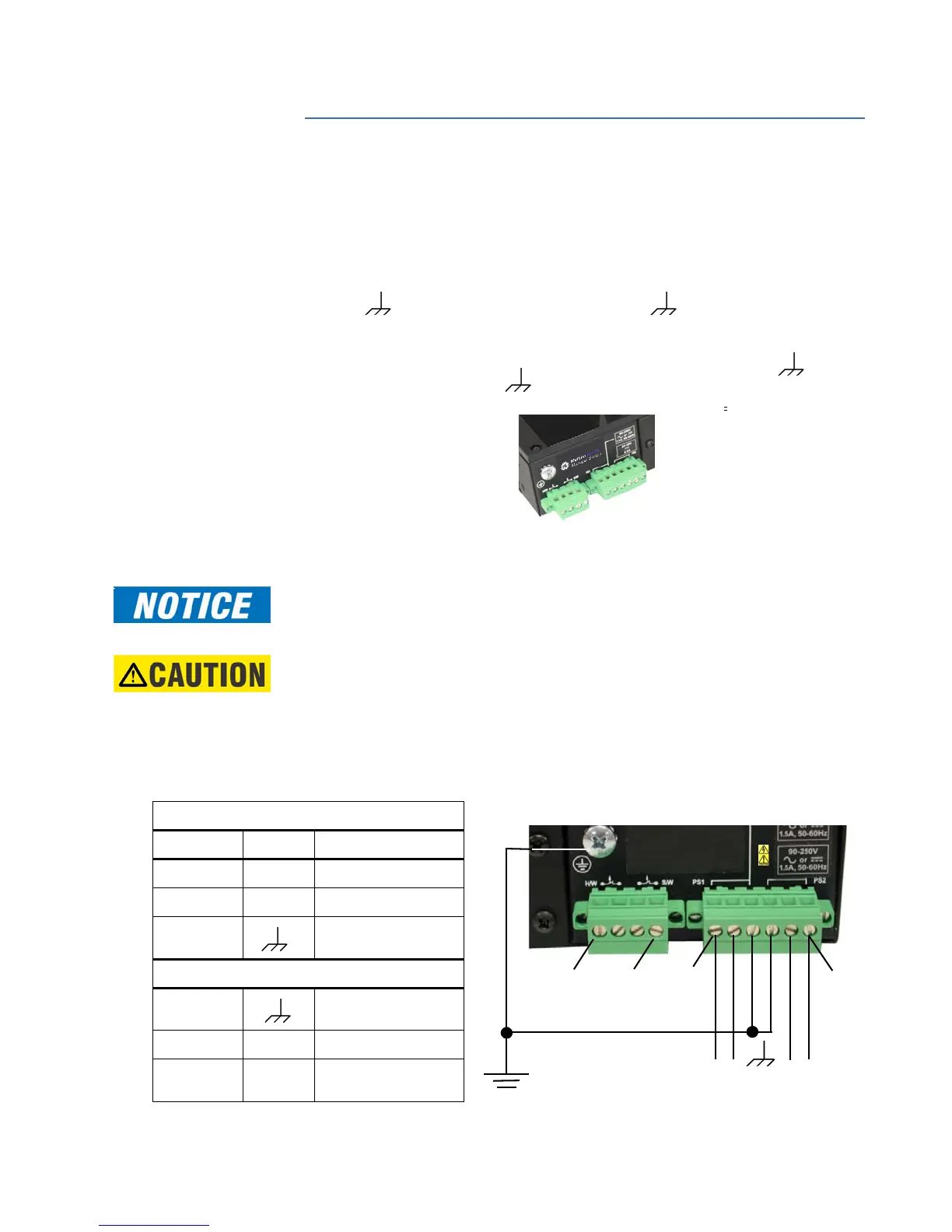
The standard high voltage (120/125 V AC/DC) or low-voltage (48 V DC) terminal block on
the ML3000 is located on the rear of the unit and is equipped with three (3) screw-down
lead posts. The power terminals for DC are identified as positive (+), negative (–), and
ground ( ) and for AC, as live L(+), neutral N(–), and . The chassis or safety ground
is the stud located beside the terminal block.
The connection procedure is straightforward. Simply insert DC leads to the ML3000 power
terminal positive (+), negative (–), or AC leads to the live L(+), neutral N(–), and . Please
ensure the correct polarity. The must be connected to the safety ground, except
during dielectric testing. Ensure that each lead is securely tightened.
FIGURE 3–1: Power connection and alarm contacts
Note
Always use a voltmeter to measure the voltage of the incoming power supply and properly
determine the positive and negative leads.
Note
The GND should be connected first. When power is applied, the green PWR LED will
illuminate.
The ML3000 is available with a redundant power supply option. If the redundant power
supply is ordered, it should be wired as described above. The possible combinations of
redundant power supplies are: HI-HI, HI-LO, LO-HI, and LO-LO. The AC power supply cannot
be supplied with a redundant supply.
Table 3–2: AC/DC Power Input
PS1 (Power Supply 1)
Figure 3-1: Power Supply:
Pin # Marking Function
Pin 1: N/- (Negative)/Neutral
Pin 2: L/+ (Positive)/Live
Pin 3: Ground
PS2 (Power Supply 2)
Pin 4: Ground
Pin 5: N/- (Negative)/Neutral
Pin 6: L/+ (Positive)/Live
Pin 1 Pin 4
14 AWG minimum
[9 inch-pound maximum pin torque]
Pin 1
Pin 6
N/-
L/+
N/-
L/+
18 AWG
minimum