CHAPTER 3: INSTALLATION INSTALLATION
MULTILINK ML3000 ETHERNET COMMUNICATIONS SWITCH – INSTRUCTION MANUAL 3–9
The alarm contacts are located to the left of the power input connection of the ML3000
unit and are green in color as shown in the picture.
Figure 3-2: Alarm Contacts:
Alarm contacts (in : (1,2) are hardware operated, and (3,4) are software operated
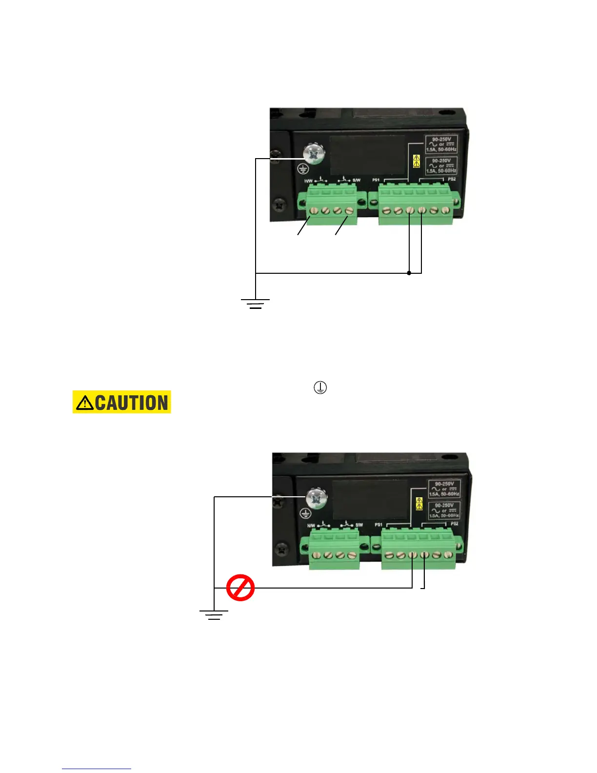
3.4.4 Dielectric Strength (hi-pot) Testing
The shorting link between the and safety ground must be removed prior to the
dielectric strength test, as shown below, to protect the transient suppression circuitry of
the power supply.
FIGURE 3–2: Dielectric strength testing