Installation 2-7
January 2006
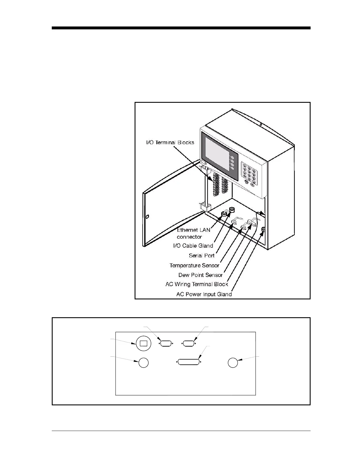
Wiring the Wall-Mount All connections to the wall-mount unit are made through the panel at
the bottom of the case as shown in Figure 2-8 below. Any I/O cabling
is brought into the unit through a gland at the lower left of the case
and connects to the terminal blocks on the left side of the case. Wiring
for these connections is shown in Figure 2-11 on page 2-8. The dew
point sensor and temperature sensor cable connectors are located near
the center of this panel.
Figure 2-8: Wall-Mount Wiring Entrance Locations
Figure 2-9: Wall-Mount Bottom Panel (viewed from under the unit)
DEW POINT
Gland for
I/O Wiring
IN/OUT
LAN
COM
Optional Ethernet
LAN Connector
Serial Port
Dew Point Sensor
Gland for
AC Power
Wiring
4 ASB 250V TYPE T
90/250 VAC 47-63 Hz
AC LINE
TEMP
Temperature Sensor