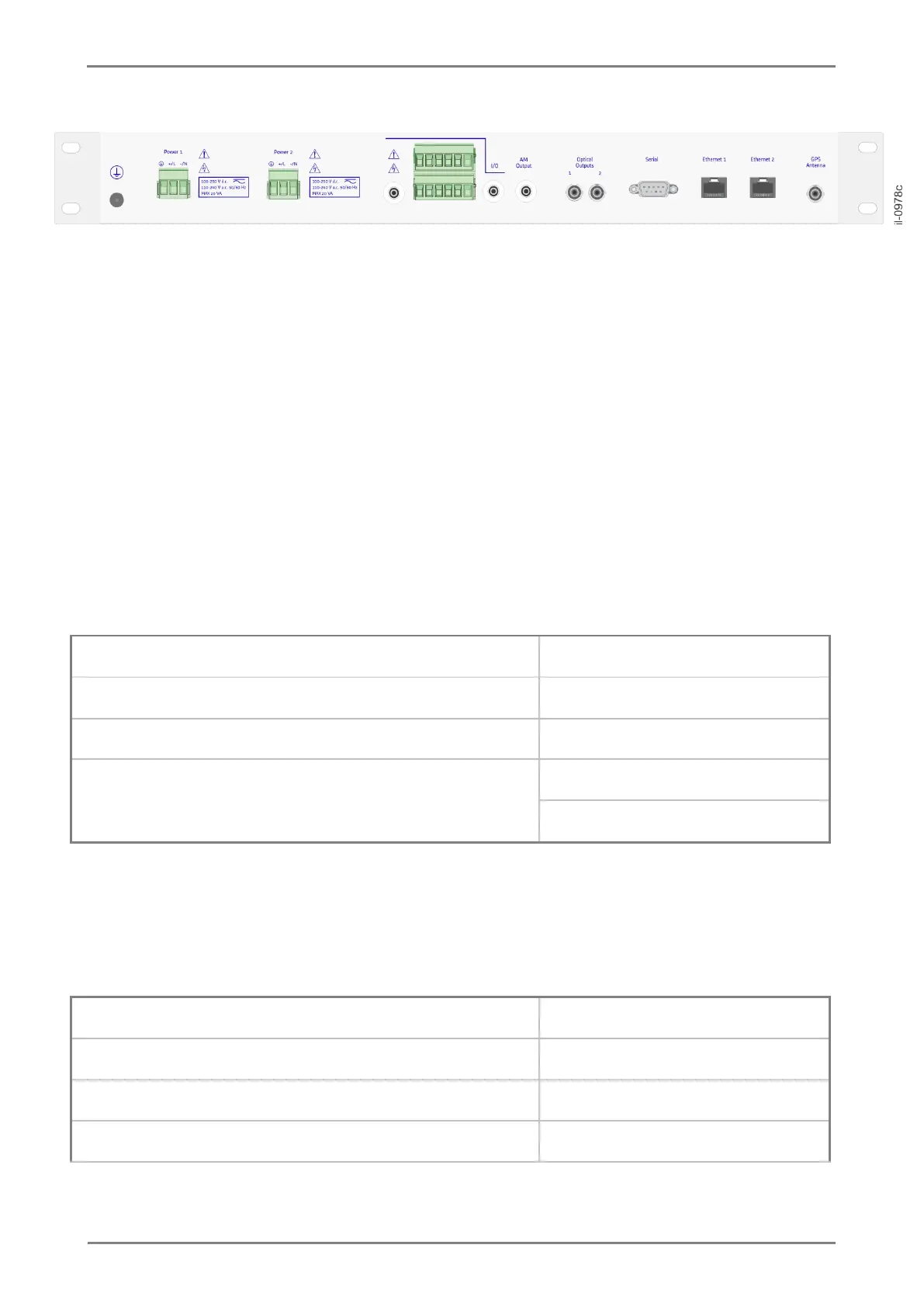
Figure 2: Rear view of the RT430
The rear panel of the RT430 comprises two feeding inputs, AC or DC; two BNC connector electrical outputs
for synchronization, one of them insulated; two TTL level screw connector electrical outputs for
synchronization, one of them insulated; two open collector outputs; LOCKED contactor relay and one
CMOS/TTL level input; one amplitude-modulated output for IRIG-B124 signal; two optical outputs; RS232
and RS422/485 serial ports; Ethernet network communication ports and GPS antenna input.
For information on installing the equipment, access Chapter 2.
1.6 Technical Specifications
1.6.1 Power Supply
TABLE 3: Power supply specifications.
Operating nominal voltage
100-250 V dc, 110- 240 V ac
1.6.2 GPS Antenna Input
TABLE 4: GPS Antenna input specifications for temporal synchronizationl.
GPS L1 (1575.42 MHz), C/A code
152 dBm (After acquisition)
142 dBm (During acquisition)