3. COMMUNICATION
3.1 Communication
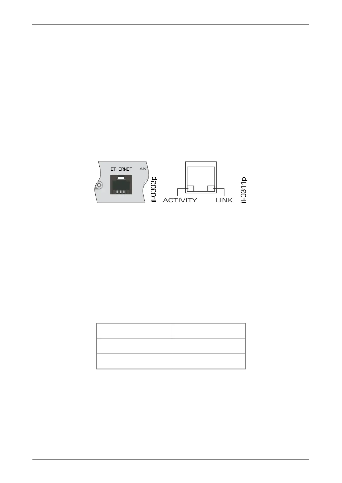
RT430 has 2 Ethernet 10/100BaseT communication interfaces with RJ45 connector ETHERNET 1 and
ETHERNET 2 enabling redundancy. Figure 23 shows one of the electrical communication interfaces.
Connect a CAT5 cable with a RJ45 connector in each port. The LINK led indicates that the cable is
transmitting signal, and the ACTIVITY led blinks when there is data exchange.
Figure 23: Electrical communication interface via Ethernet network
The Ethernet 1 communication interface can also be enabled to send PTP synchronism messages,
according to the unit model as Chapter 1 presents. For PTP protocol configuration details, see Chapter 4.
3.2 Factory default settings
Factory defaults for Ethernet ports are listed below:
TABLE 25: Ethernet 1 port are listed below.