2.4 Environment
Temperature and relative humidity should not exceed the limits stated in Chapter 1. We recommend you to
provide appropriate heating or cooling measures to ensure that these limits are respected at all times.
2.5 Mounting
RT430 has been designed to be mounted in a standard 19-inch rack using four M6x15 screws to affix. Allow
adequate clearance for all connections. In particular, the optical fiber cables should be installed respecting
the 30mm minimum bending.
For more information about the equipment dimensions, access Chapter 1.
2.6 Connectors
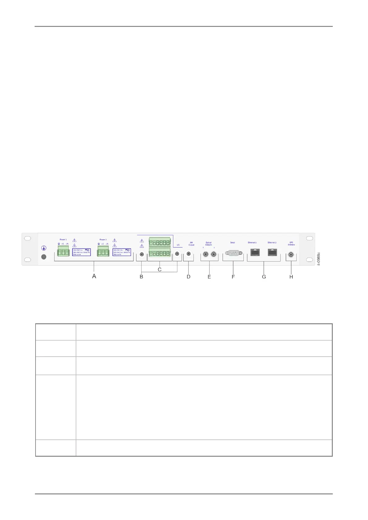
Components and connectors of RT430’s rear panel are shown in Figure 5.
Figure 5: Rear panel connectors
TABLE 20: Connectores do painel posterior do equipamento.
2 electrical outputs for synchronism with BNC connector, one of them insulated
2 electrical output for synchronism with TTL level screw connector, one of them
insulated;
2 open collector output;
LOCKED contactor relay;
And 1 CMOS/TTL level even input.
1 modulated-amplitude output for IRIG-B124 signal