GE_UPS_OPM_TLE_SCE_M60_M80_1GB_V020.docx
User Manual TLE Series 600 & 800 CE S1
8.2 PROCEDURES SINGLE TLE SERIES 600 & 800 FUNCTIONING AS
FREQUENCY CONVERTER
When the TLE Series 600 & 800 functions as a Frequency Converter, the Automatic Bypass and Manual
Bypass (only if provided by customer) functions are disabled.
Therefore the Load cannot be transferred to Mains in case of overload, short circuit, or Inverter failure.
In situations where the UPS needs to be shut-down for maintenance purposes, also the Load must be
shut-down or disconnected.
8.2.1 Initial Start-up of the TLE Series 600 & 800 as frequency converter
WARNING !
Before proceeding to turn on the UPS system, ensure that the AC and DC external
isolators are OFF, and prevent their inadverted operation.
Ensure that the Output Load distribution can be powered and all the Output
Isolators are open.
Open the front door and make sure that:
All the connections to the input/output terminals or bus bars of the UPS have been made correctly.
The safety screens are fixed in their position.
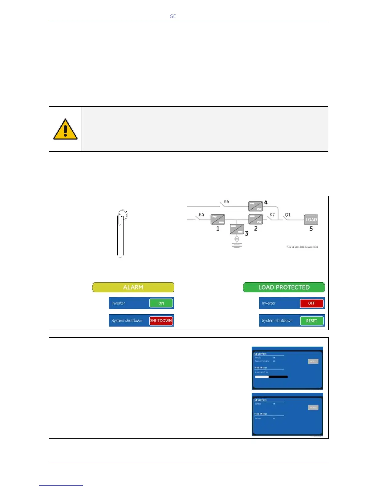
The switch “Q1 –UPS Output” is open (Pos. O) and the “External Battery Protections” must be open
(Pos. O).
LED 1 Rectifier
LED 2 Inverter
LED 3 Booster/ Battery charger
LED 4 Automatic Bypass
LED 5 LOAD on UPS
Command
System shutdown RESET
1.
Switch-ON the Mains voltage from the input distribution.
The UPS performs a “Self-test”.
A successful termination of the tests will be indicated with Overall test
results “OK”.
Commissioning cannot be continued should one or more tests result to
be negative. Please contact in this case your Service Centre.
At this stage the Electronic Power Supply and Control Panel are switched
ON and the Buzzer sounds.
Press “MUTE” key to reset Acoustical Alarm.
LED ALARM remains lit.
TLES_UL_1000_S1_Switch Q1_01
Q1
0 OFF
I ON


 To Next Page