GE_UPS_OPM_TLE_SCE_M60_M80_1GB_V020.docx
User Manual TLE Series 600 & 800 CE S1
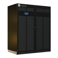
5.9.1 TLE Series 600 - Power connection with Common Mains Input
Fig. 5.9.1-1 TLE Series 600 - Power connection with common Mains Input
Power connection cables are connected to bus bars using M12 bolts.
The bolts of the connection cables must be tightened with a torque wrench at 60 Nm.
Fix the cables on accessory “A” with the enclosed cable ties.
Common Mains Input - Rectifier / Bypass
Rectifier + Bypass Phase L1
Rectifier + Bypass Phase L2
Rectifier + Bypass Phase L3
NOTE !
The interconnection links BR1, BR2 and BR3 on the input bus bars MUST REMAIN
CONNECTED (see Fig. 5.9.1-1).
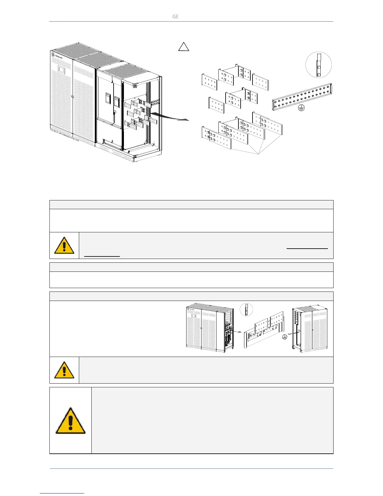
External Battery connection
Positive pole of the battery
Negative pole of the battery
Bolt Size / Torque: M10 / 40 Nm
DANGER !
Before closing the “External Battery Fuses”, verify for correct polarity of the External
Battery connection.
NOTE !
To meet standards concerning electromagnetic compliance, the connection
between the UPS and external Battery must be done by using a shielded cable or
suitable shielded (steel) conduit!
This UPS is only designed to operate in a wye-configured electrical system with a
solidly grounded neutral.
If the UPS is equipped with an input bypass transformer, the secondary of the
transformer must be wye-configured with neutral solidly grounded.
Position of the bus bars for
cables input from the top of the UPS (see Section 5.9)
Load
L3
Load
L2
Load
L1
BR3
BR2
BR1
INTERCONNECTIONS LINKS
BR1, BR2 and BR3
MUST REMAIN CONNECTED
PE
!
L2-1
L3-1
N
Mains Neutral
Load Neutral
N
Mains Neutral
Load Neutral
1
Rectifier
Mains
Q1
Typical installation
using common NEMA
two hole lugs
A
L1-1
Typical installation
using common NEMA
two hole lugs
TLES_800_S1_UPS connection battery_01GB
Power Section cabinet
+
_
In/Out Section cabinet
PE

 Loading...