GE_UPS_OPM_TLE_SCE_M60_M80_1GB_V020.docx
User Manual TLE Series 600 & 800 CE S1
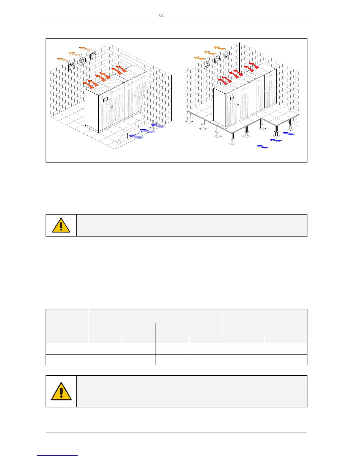
5.5 VENTILATION AND COOLING
Fig. 5.5-1 Installation on plain floor
Fig. 5.5-2 Installation on raised floor
The heat produced by the UPS is transferred to the environment by its ventilation.
Air inlets for UPS ventilation are located on the front of the UPS, while air outlets are on top of the
cabinet.
A suitable ventilation or cooling system must be installed to extract the heat from the UPS room.
NOTE !
Do not put anything on the top of the cabinet.
Air filtering systems could be required when the UPS operates in a dirty environment.
In order to prevent overheating of the UPS, the available air intake flow rate must exceed the total air
exhaust flow rate requirement of the UPS system.
Contact your Dealer or the nearest Service Centre for appropriate solutions.
The below table indicates the heat dissipation at full Load at PF = 0.9 & 1 and charged Battery, up to
1000 m (3280 ft) altitude, for cooling air 25°C (77°F) to 30°C (86°F).
NOTE !
Even when eBoost™ Operating Mode option is available, the ventilation and cooling
system shall be rated as for operation in VFI mode.
Air Extraction
Air Intake
TLES_600-800_S1_UPS ventilation_Raised floor_01GB
Air Intake
TLES_600-800_S1_UPS ventilation_Raised floor_01GB
Air Extraction