GE_UPS_OPM_TLE_SCE_M60_M80_1GB_V020.docx
User Manual TLE Series 600 & 800 CE S1
5.11 EPO COMMAND CONNECTION (EMERGENCY POWER OFF)
WARNING !
The connection of an emergency button EPO (Emergency Power Off) must be
performed by QUALIFIED SERVICE PERSONNEL only when the UPS is
COMPLETELY POWERED DOWN.
BE AWARE !
The reliability of the system depends on this contact NC (Normally Closed)!
An Emergency button (Normally Closed voltage-free contact) can be connected on terminals XA /
EPO-1, EPO-2. Max. rating XA terminals: 2.5mm
2
.
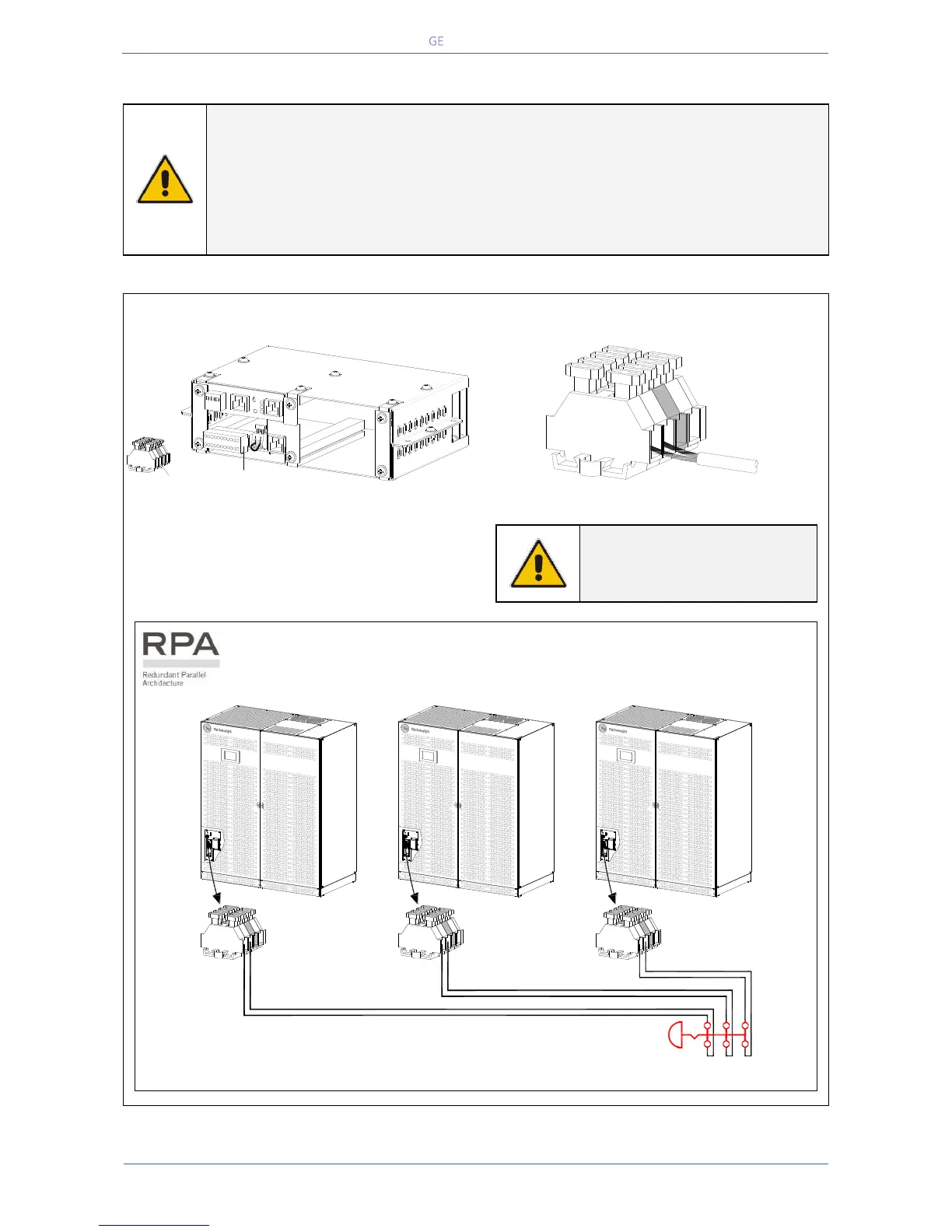
Fig. 5.11-1 XA terminal block for EPO command connection
When opened, this contact causes the immediate
opening of the Contactors K6 and K7 as well as
the shut-down of Rectifier, Inverter and Static-
Switch.
NOTE !
This procedure could imply a
Load shut-down.
In a Parallel System a separate NC (Normally Closed) contact must be connected
individually to each unit.
Fig. 5.11-2 XA “EPO - Emergency Power Off” – RPA Parallel System connection schematics
TLES_160-400_S1_Customer interface-XA_01
Customer Interface
XA
EPO
EPO
+
-
1
12
13
14
15
16
17
18
19
20
21
22
2
3
4
5
6
7
8
9
10
11
SGSE_400-500_S3_Terminals XA_01
XA
EPO
EPO
+
-
TLES_600_S1_UPS_EPO-RPA connection schematic_GE_01
EPO
EPO
+
-
EPO
EPO
+
-
EPO
EPO
+
-
XA XA XA
EPO
12
-
+
12
-
+
12
-
+
 Loading...