GE_UPS_OPM_TLE_SCE_M60_M80_1GB_V020.docx
User Manual TLE Series 600 & 800 CE S1
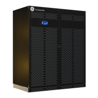
Fig. 5.10.3-4 TLE Series 600 - Control Bus cable routing and connection
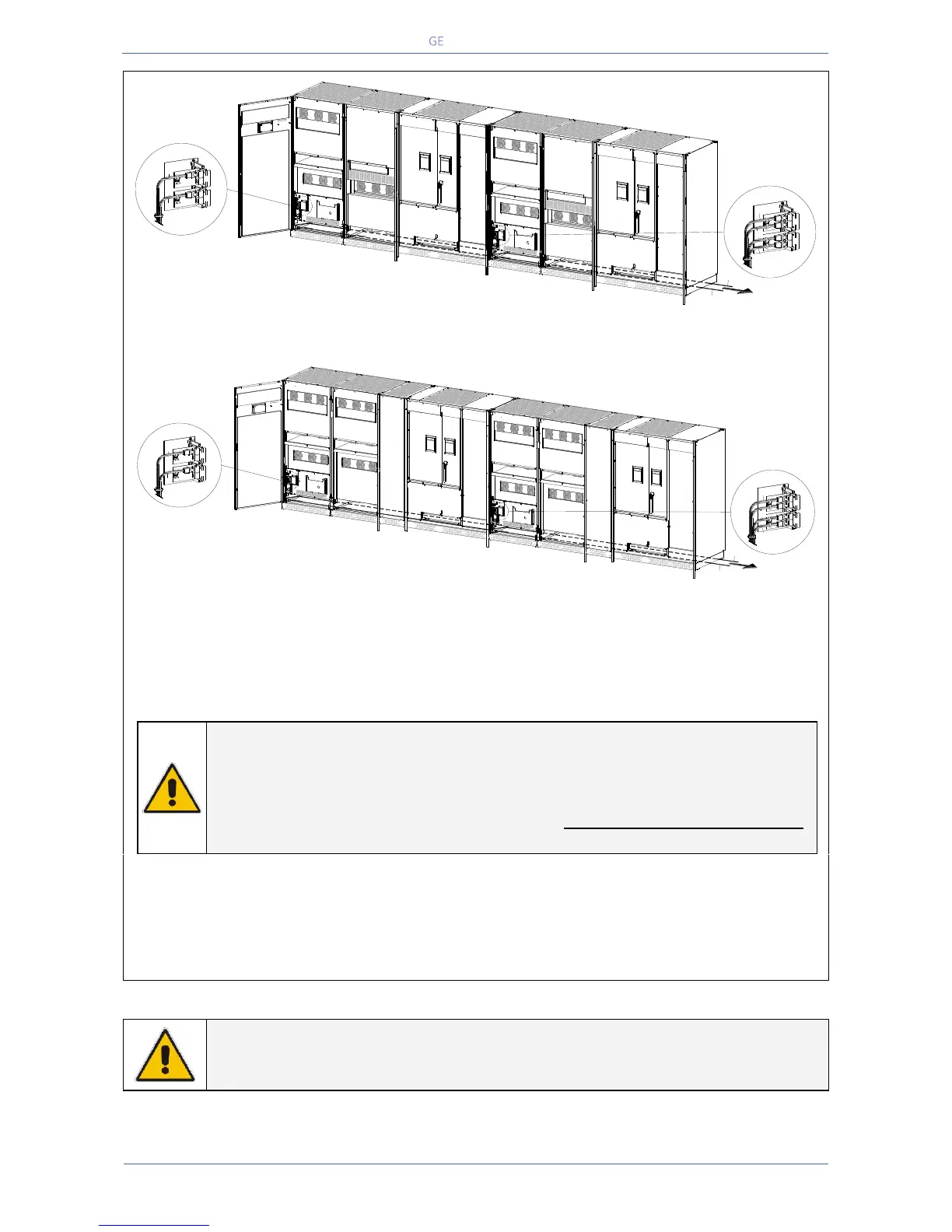
Fig. 5.10.3-5 TLE Series 800 - Control Bus cable routing and connection
Control bus cables routing
Place and fix the cables J1A – J2A (1/2/3/4/5) and J1B – J2B (1/2/3/4/5) inside the UPS cabinets in
the position illustrated in the drawing Fig. 5.10.3-4 and 5.10.3-5.
NOTE !
Pay attention when cabling and routing the communication bus cables J1A – J2A
(1/2/3/4/5) and J1B – J2B (1/2/3/4/5) inside the UPS cabinet.
In case one unit must be removed from the Parallel System, the communication
bus cables must be taken out the UPS cabinet WITHOUT DISCONNECTING THEM
from the two boards “P13/P14 – IM0222 – Bus Interface Board”.
For reliability reasons the cables J1A – J2A (1/2/3/4/5) and J1B – J2B (1/2/3/4/5) connecting the units
should be run in separated protected conduits (as indicated in Fig. 5.10.3-4 and 5.10.3-5) separated
from the power cables.
It is important that the cable J1A – J2A (1/2/3/4/5) must be the same length as cable J1B – J2B
(1/2/3/4/5).
WARNING !
Connection and commissioning of an additional UPS to an existing Parallel System
must be performed by a service engineer from of your Service Centre.
TLES_600_S1_RPA connection_03GB
-
+
12
Q1
0 OFF
I ON
J2
J1
J2
J1
B
A
J1A/1
J1B/1
UPS 1
-
+
12
Q1
0 OFF
I ON
UPS 2
UPS 1
J2
J1
J2
J1
B
A
J1A/1
J1B/2÷5
J1B/1
J1A/2÷5
UPS 2/3/4/5
UPS 3, 4, 5, 6
J1B/2÷5
J1A/2÷5
TLES_800_S1_RPA connection_03GB
J2
J1
J2
J1
B
A
J1A/1
J1B/1
UPS 1
UPS 1
J2
J1
J2
J1
B
A
J1A/1
J1B/2÷5
J1B/1
J1A/2÷5
UPS 2/3/4/5
UPS 3, 4, 5, 6
J1B/2÷5
J1A/2÷5
-
+
12
Q1
0 OFF
I ON
-
+
12
Q1
0 OFF
I ON
UPS 2
 Loading...