GE_UPS_OPM_TLE_SCE_M60_M80_1GB_V020.docx
User Manual TLE Series 600 & 800 CE S1
7.3.1 Events (alarms and messages)
Each of the following listed events, alarm or message, can be displayed on the LCD screen, on a PC with
the software “GE Data Protection” installed or with the monitoring system “GE iUPSGuard”.
Alarms and Messages are differently specified because the alarms are indicating an abnormal
functioning of the UPS (which are additionally signalled with the LED ALARM and acoustically with the
buzzer), while the messages indicate the various states of operation of the UPS (stored in the events list,
but not activating the LED ALARM and the acoustical alarm).
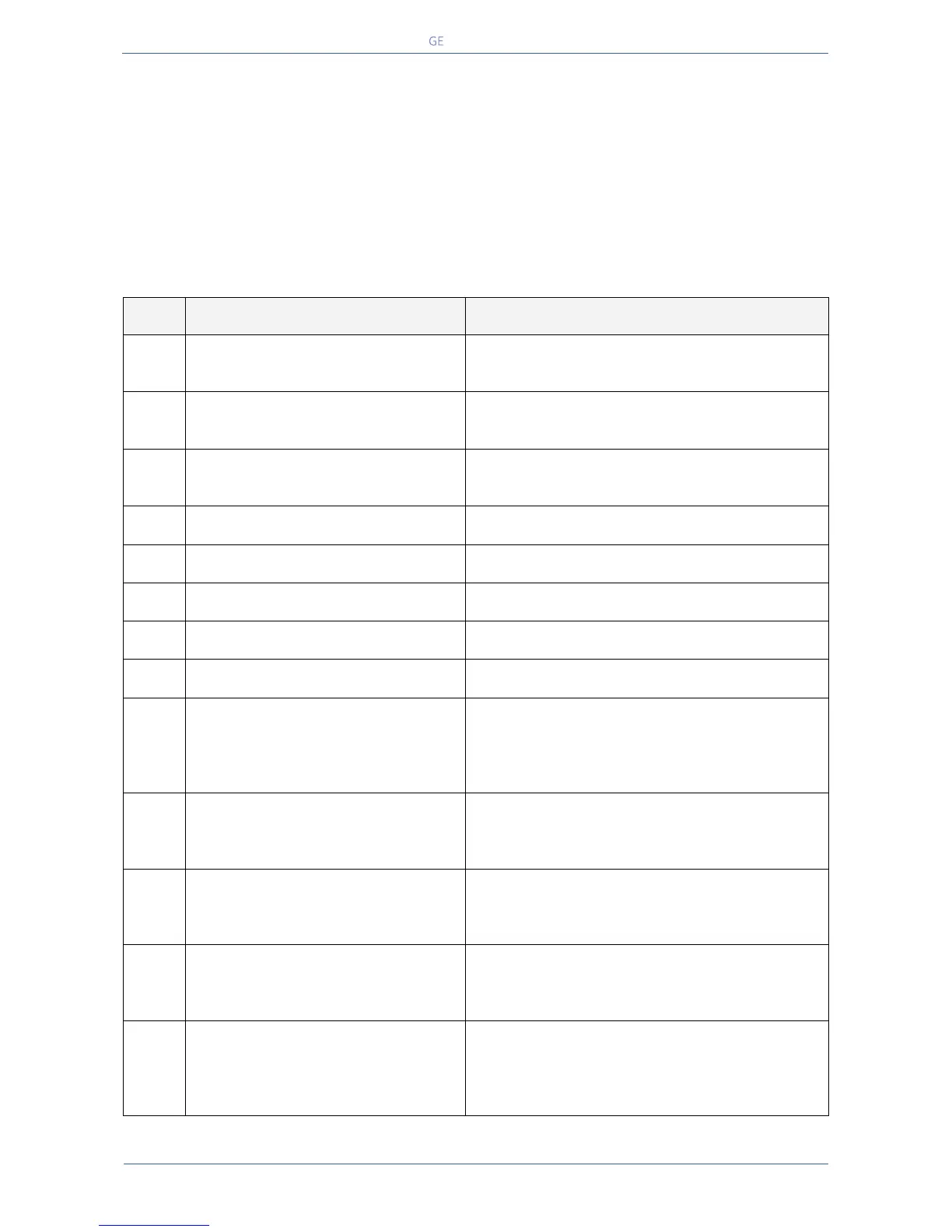
7.3.2 Alarms list
Parameters are lost and have been replaced with
default values.
Please call nearest Service Centre for intervention.
A blocked DSP on the Control board causes this
alarm, and consequently the shut-down of Rectifier
and inverter and the opening of K3.
UPS FAILURE ON PARALLEL SYSTEM
The master unit detected the slave unit missing on
the communication bus even though switch Q1 is
still closed.
The parallel communication bus system is subject
to high errors rate on channel JA.
The parallel communication bus system is subject
to high errors rate on channel JB.
There is an interruption in the channel JA of the
parallel communication bus system.
There is an interruption in the channel JB of the
parallel communication bus system.
The connectivity communication bus is faulty or
interrupted.
The u-switch mounted on the Rectifier input fuses
indicates a blown fuse, and consequently it is shut
down.
Clearance of this condition allows you to restart
the Rectifier.
K4 not closed despite a closing command being
issued.
Signalled by auxiliary contact. Rectifier cannot
start.
K4 not open despite an opening command being
issued.
Signalled by auxiliary contact.
Mains remains connected to Rectifier bridge.
This function, when enabled on input
programmable relays (password required), warns
the user about the external Battery Fuses failure or
MCB opening, signalled by NO free contact.
RECTIFIER OVERTEMPERATURE
Temperature sensor indicates a situation of
overtemperature on the Rectifier bridge.
Only the alarm is given.
The Rectifier, when in an Off state, cannot start as
long as this condition persists.
 Loading...