GE_UPS_OPM_TLE_SCE_M60_M80_1GB_V020.docx
User Manual TLE Series 600 & 800 CE S1
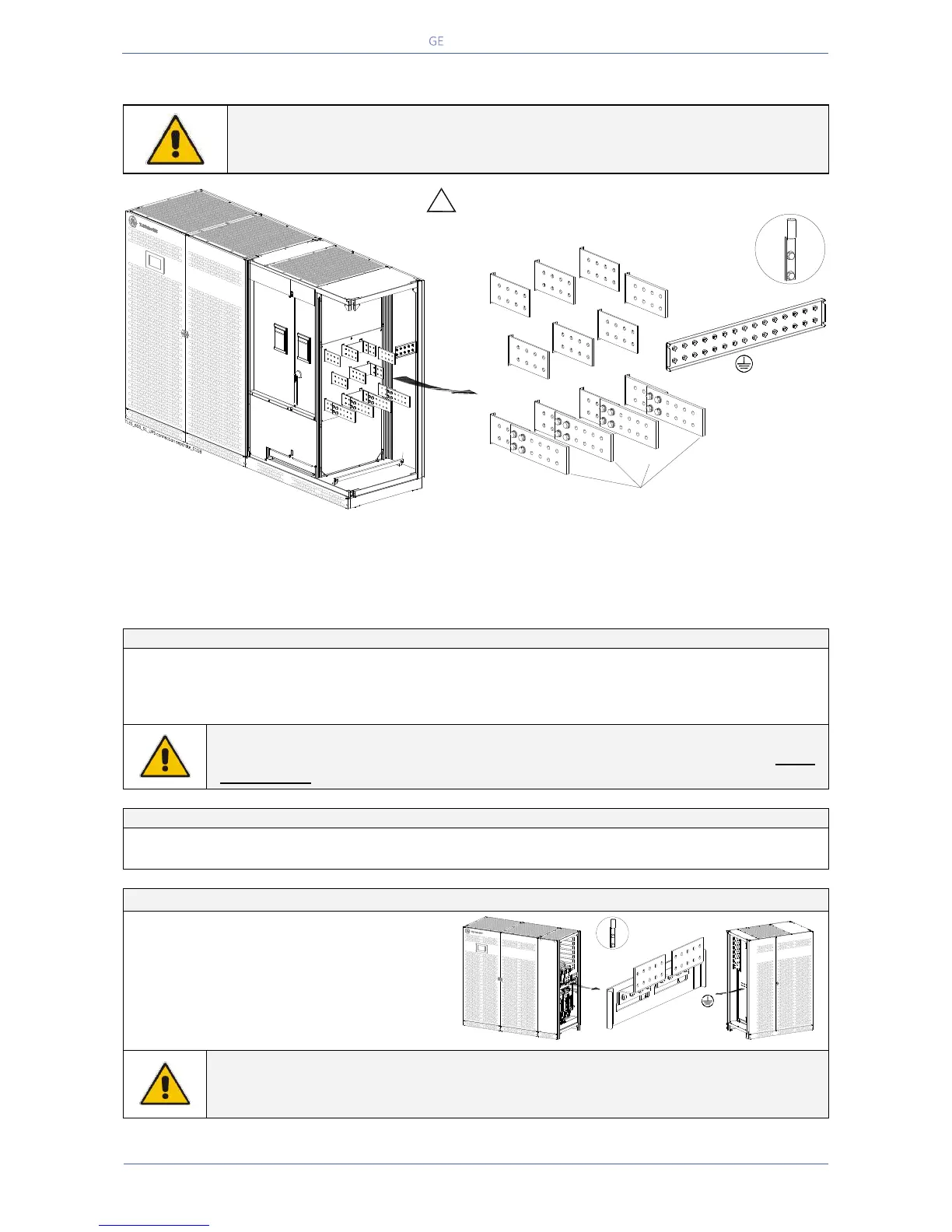
5.9.2 TLE Series 600 - Power connection with Separate Mains Input
NOTE !
Connect a single input Neutral to Bypass Mains (inside the UPS, common Neutral
for Bypass and Rectifier).
Fig. 5.9.2-1 TLE Series 600 - Power connection with Separate Mains Input
Power connection cables are connected to bus bars using M12 bolts.
The bolts of the connection cables must be tightened with a torque wrench at 60 Nm.
Fix the cables on accessory “A” with the enclosed cable ties.
Separate Mains Input - Rectifier / Bypass
NOTE !
In this case, the interconnection links BR1, BR2 and BR3 on the input bus bars MUST
BE REMOVED. See Fig. 5.9.2-2.
External Battery connection
Positive pole of the battery
Negative pole of the battery
Bolt Size / Torque: M10 / 40 Nm
DANGER !
Before closing the “External Battery Fuses”, verify for correct polarity of the External
Battery connection.
PE
!
Q1
Position of the bus bars for
cables input from the top of the UPS (see Section 5.9)
Load
L3
Load
L2
Load
L1
L1-2
L2-2
L3-2
N
Mains Neutral
Load Neutral
N
Mains Neutral
Load Neutral
1
Rectifier
Mains
2
Bypass
Mains
INTERCONNECTIONS LINKS
BR1, BR2 and BR3
MUST BE REMOVED
(see Fig 5.9.2-2)
L1-1
L2-1
L3-1
Typical installation
using common NEMA
two hole lugs
A
Typical installation
using common NEMA
two hole lugs
TLES_800_S1_UPS connection battery_01GB
Power Section cabinet
+
_
In/Out Section cabinet
PE