GE_UPS_OPM_TLE_SCE_M60_M80_1GB_V020.docx
User Manual TLE Series 600 & 800 CE S1
WARNING !
UPS installation and connection must be performed by QUALIFIED SERVICE
PERSONNEL only.
Refer to the “Safety prescriptions - Installation” described on Section 1.
5.8.1 Mains input connection
NOTE !
Ensure that the AC and DC external isolators are OFF and locked out to prevent their
inadvertent operation.
Do not apply power to the equipment prior to the commissioning by a QUALIFIED
SERVICE ENGINEER.
Before any other input connection, connect and check the earthing wire.
The Mains input power connection can be common or separate for Bypass supply and Rectifier input,
depending on the electrical system provided by the customer.
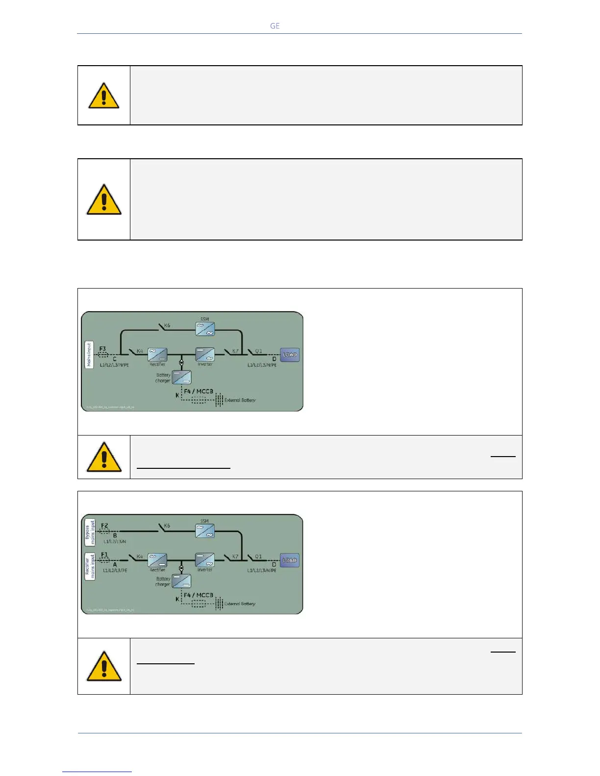
Common mains input Rectifier & Bypass
Fig. 5.8.1-1 Common mains input Rectifier & Bypass
The same power source is to be used for both
Bypass supply and Rectifier input (input F3).
Bear in mind that when the Mains fuses are
opened there is a supply failure to the Rectifier
as well as to the Automatic Bypass and
Manual Bypass switch (only if provided by
customer).
In this case, the interconnection links BR1, BR2 and BR3 on the input bus bars MUST
REMAIN CONNECTED. See Fig. 5.9.1-1 and 5.9.3-1.
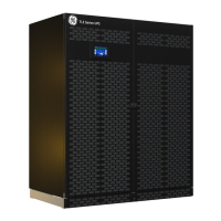
Separate mains input Rectifier & Bypass
Fig. 5.8.1-2 Separate mains input Rectifier & Bypass
The Bypass and Rectifier use different power
sources (F1 and F2 inputs).
In this case, when the Rectifier-input fuses are
opened, the Automatic Bypass and the
Manual Bypass (only if provided by customer)
are supplied by the other connection.
In this case, the interconnection links BR1, BR2 and BR3 on the input bus bars MUST
BE REMOVED. See Fig. 5.9.2-2 and 5.9.4-2.
Connect a single input Neutral to Bypass Mains (inside the UPS, common Neutral for
Bypass and Rectifier).