GE_UPS_OPM_TLE_SCE_M60_M80_1GB_V020.docx
User Manual TLE Series 600 & 800 CE S1
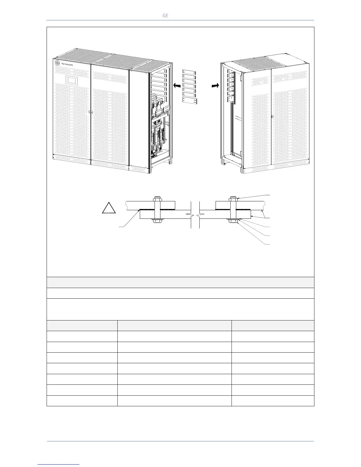
TLE Series 800 - Bus bars interconnection
Fig. 5.7.2-2 TLE Series 800 – Bus bars interconnection
Description of connection
Interconnection L1 Inverter
Interconnection L2 Inverter
Interconnection L3 Inverter
Interconnection L1 Rectifier
Interconnection L1 Rectifier
Interconnection L1 Rectifier
Interconnection N - Neutral
1 Bus bar 100/10 x 270 mm
In/Out Section cabinet
Detail showing bus bars interconnection
M10 Pre Fixed Nut
M10 Flat Washer
M10 Spring Washer
M10x35 Bolt
Bus Bar
Bus bars interconnection
L1 Inverter
L2 Inverter
L3 Inverter
L1 Rectifier
N - Neutral
L2 Rectifier
L3 Rectifier
TLES_800_S1_UPS connection cabinets_GE_02GB
Power Section cabinet
Use the dedicated
conductor termination compound.
Example: PENETROX E
manufactured by BURNDY
!