GE_UPS_OPM_TLE_SCE_M60_M80_1GB_V020.docx
User Manual TLE Series 600 & 800 CE S1
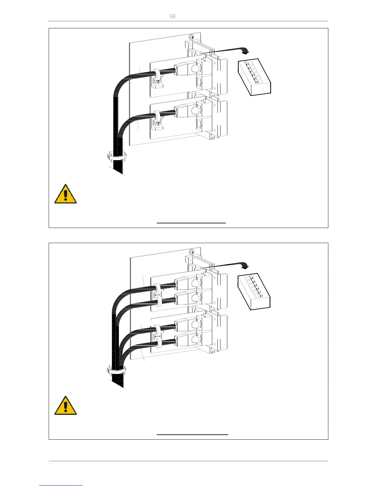
Fig. 5.10.2-2 Bus connection on first and last units
Final units, first and last, of a RPA Parallel System
On the two boards P13/P14 – IM0222 – Bus Interface Board, of the first and last units of a Parallel
System, the switches SW1-1/2/3/4/5/6 MUST BE IN POSITION ON (see Fig. 5.10.2-2).
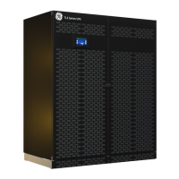
Fig. 5.10.2-3 Bus connection on intermediate units
Intermediate units of a RPA Parallel System
On the two boards P13/P14 – IM0222 – Bus Interface Board, of the intermediate units of a Parallel
System, the switches SW1-1/2/3/4/5/6 MUST BE IN POSITION OFF (see Fig. 5.10.2-3).
J2
J1
J2
J1
B
A
J1A/1
J1B/1
1
2
3
SW1
4
5
6
ON
TLES_160-400_S1_RPA-IM0222_02
J2
J1
J2
J1
B
A
J1A/1
J1B/2÷5
J1B/1
J1A/2÷5
1
2
3
4
5
6
ON
SW1
TLES_160-400_S1_RPA-IM0222_03