Chapter 2. Instrument Setup
USM Go Operator’s Manual 47
2.4.8 Selecting a Rectification Mode
Rectification effects the orientation of the A-scan on the display screen. The A-scan represents the sound pulse (i.e. echo) that is returned to
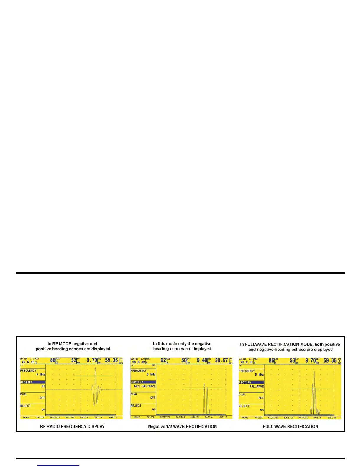
the instrument from the material being tested. The series of echoes looks like the Radio Frequency (RF) signal shown in Figure 12 below.
Note that the RF signal has both a negative component below the axis and a positive component above the axis. In RF mode, Gate A and
Gate B can be positioned either above or below the axis, to be triggered by either a positive-heading echo or a negative-heading echo.
Figure 12: Typical RF and Rectified Signals

 Loading...


