Handling and assembly
Axle assembly
2018-9015-001
09-2016
40 / 192
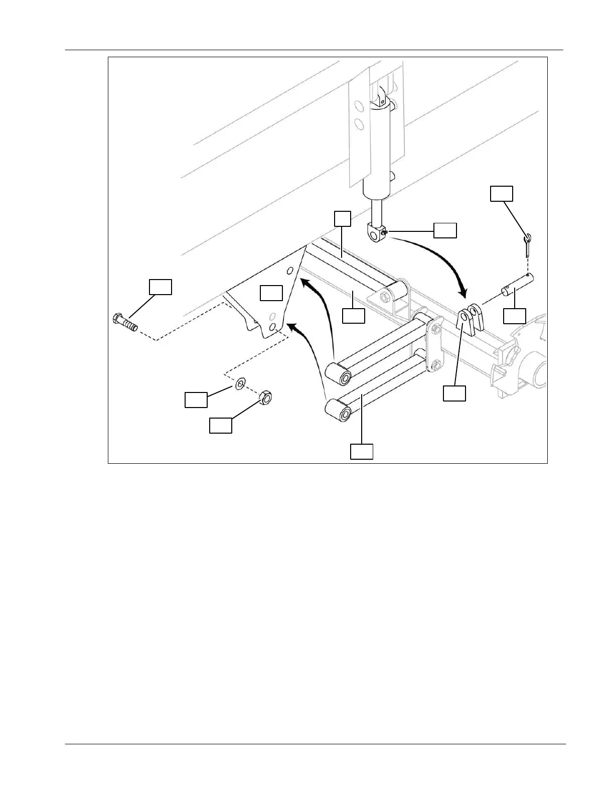
16
19
5
12
14
13
15
10
11
18
17
● Lift the axle (10) using the floor jack;
● Align the suspension cylinder (12) hole with the bracket (11) holes then
insert a connecting rod (13) through the holes. Secure the connecting rod
using cotter pins (14) on both sides;
● Insert the four arms (15) between the plates (16). Fix the arms using bolts
(17), washers (18) and nuts (19). Torque to 350 ft-lb [475 NM];
● Position the transverse arm (5) end in the bracket located under the
spreader and fix it using bolt, washer and nut (not illustrated). Torque to 350
ft-lb [475 NM].
 Loading...