Handling and assembly
Air braking system assembly (optional)
2018-9015-001
09-2016
48 / 192
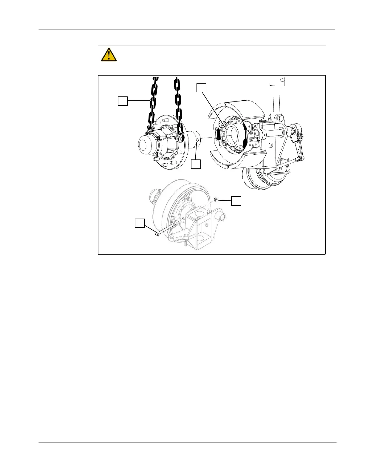
5.7.2 Wheel hub assembly
Attention!
To lift wheel hub, use a lifting device with a minimum lifting capacity of
150 lbs [70 kg].
2
1
3
5
4
● Apply a very thin layer of grade 2, 880 Crown and Chassis grease in the
receptacle (1) using a brush;
● Lift the wheel hub using safety chains (2). Secure the safety chains with two
wheel nuts, as illustrated;
● Rotate the hub shaft to position the hub holes (3) horizontally;
● Insert the hub shaft in the receptacle (1) making sure the hub holes (3) are
aligned with the holes of the receptacle;
● Insert the cam bolt (4) through the receptacle (1) and the hub shaft (3) and
secure with a locknut (5);
● Grease the hub shaft behind the brake lining assembly through the grease
fitting;
● Repeat these steps for each wheel.