13
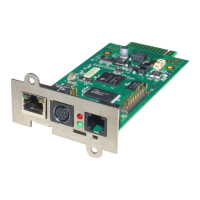
is at present. The yellow LED displays the network traffic. If the yellow LED is
glowing steady, the network traffic is too high.
2) COM2 port as Mini 8 connector for the configuration or connection of external
devices.
3) LED state of the CS121 HW131: The following tables are valid for the CS121
HW131!
Adapter is looking for UPS/initializing. The start phase can
last up to 3 minutes
Data flow/normal mode of the UPS
Communication to UPS interrupted
Operating Condition CS121 HW 131
Start procedure 1, unpacking of the OS
red flashing, green off, if an error
occurs, the red will glow steady
Start procedure 2, reboot of the OS
If the red and green LED shine at your CS121
HW131 during the reboot, huge broadcast traffic into
your network is present „recieve buffer overflow“.
The green LED is signalizing at the reboot, that the
„traffic buffer“ is full. Advice: You should filter
broadcasts via your switch, because it comes to
performance losing of the CS121 HW131
unnecessary.
red AND green during reboot
green flashing, displays the poll
interval to the UPS
4) AUX, in- or output for potential-free contacts, relays
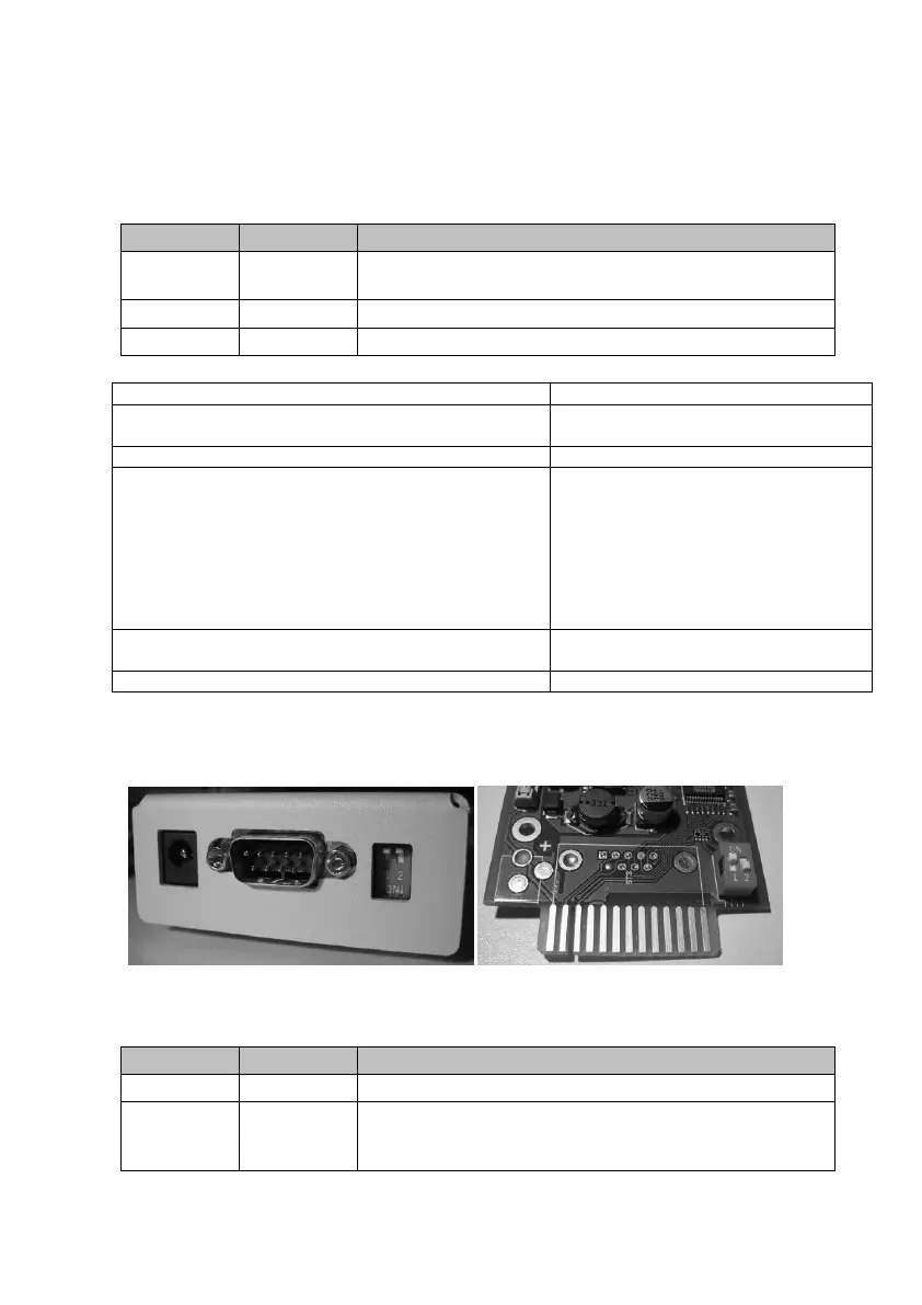
5) DIP Switches: The DIP Switches differ 2 functions; the configuration mode and the
normal operation with optional DHCP.
Figure 3: CS121L (left) in configuration mode (IP 10.10.10.10) and CS121SC (right)
in normal mode
Normal operation, device runs on the configured IP-address
Configuration mode with default IP address
10.10.10.10 and active COM 2 configuration for Terminal
software