B: Net Sizing and Sensor Layouts
123
Geodesic Sensor Net Technical Manual
S-MAN-200-GSNR-001 • January 31, 2007
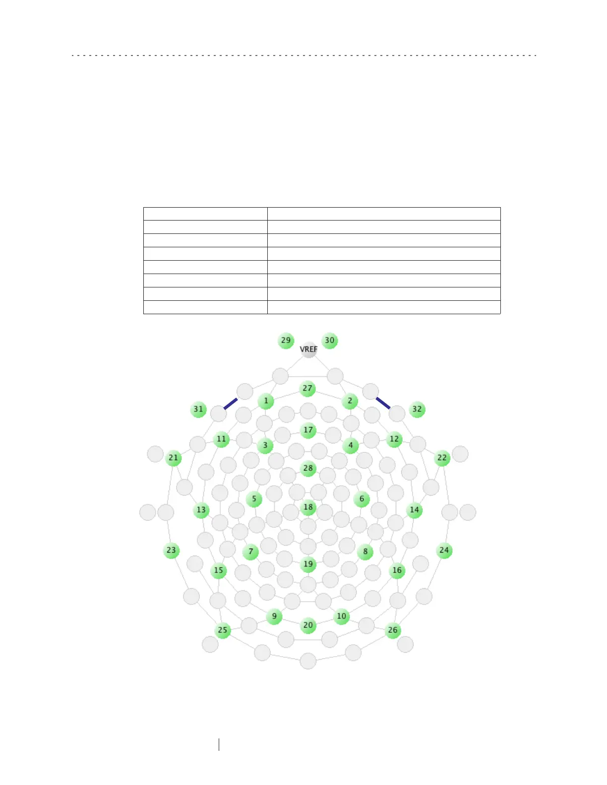
Table B-3 is a guide to the sensor layouts contained in this appendix. The thick blue
lines in each layout indicate proper thumb placement for the initial application (see
Table 6-1 on page 65).
Table B-3. Sensor layouts
Page number Sensor layout
page 123 32-channel HCGSN v.1.0
page 124 64-channel HCGSN v.1.0
page 125 128-channel HCGSN v.1.0
page 126 256-channel HCGSN v.1.0
page 127 64-channel GSN 200 v.2.0
page 128 128-channel GSN 200 v.2.1
page 129 256-channel GSN 200 v.2.1
Figure B-1. 32-channel HCGSN v.1.0