C: GSN Pinouts
132
Geodesic Sensor Net Technical Manual
S-MAN-200-GSNR-001 • January 31, 2007
Pinout Schematics
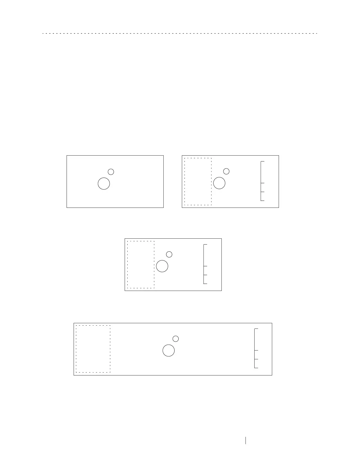
Figure C-1 provides a schematic view of the connectors in 32-, 64-, 128-, and 256-
channel Geodesic Sensor Nets. Note that the large pin in the middle occupies much
space, causing the pinout-numbering scheme to skip rows 8–12 in the 128-channel
GSN and rows 16–20 in the 256-channel GSN.
Figure C-1. Schematic view of GSN connectors
1 2 3 4 5 6 7 8 9 10 11 12 13 14 15 16 17 18 19 20 21 22 23 24 25 26 27 28 29 30 31 32 33 34 35
A
B
C
D
E
F
G
H
J
K
GND
AMP0
AMP1
AMP2
????
GSN0
GSN1
GSN2
GSN3
????
1 2 3 4 5 6 7 8 9 10 11 12 13 14 15 16 17 18 19
A
B
C
D
E
F
G
H
J
K
GND
AMP0
AMP1
AMP2
????
GSN0
GSN1
GSN2
GSN3
????
1 2 3 4 5 6 7 8 9 10 11 12 13 14 15 16 17 18 19
A
B
C
D
E
F
G
H
J
K
32 channel (no Smart Nets) 64 channel
256 channel
Note: Smart
Net pins are
located in
column 19
Note: Smart Net
pins are located
in column 32
1 2 3 4 5 6 7 8 9 10 11 12 13 14 15 16 17 18 19
A
B
C
D
E
F
G
H
J
K
GND
AMP0
AMP1
AMP2
????
GSN0
GSN1
GSN2
GSN3
????
128 channel
Note: Smart
Net pins are
located in
column 19