8: Connectivities
85
Geodesic Sensor Net Technical Manual
S-MAN-200-GSNR-001 • January 31, 2007
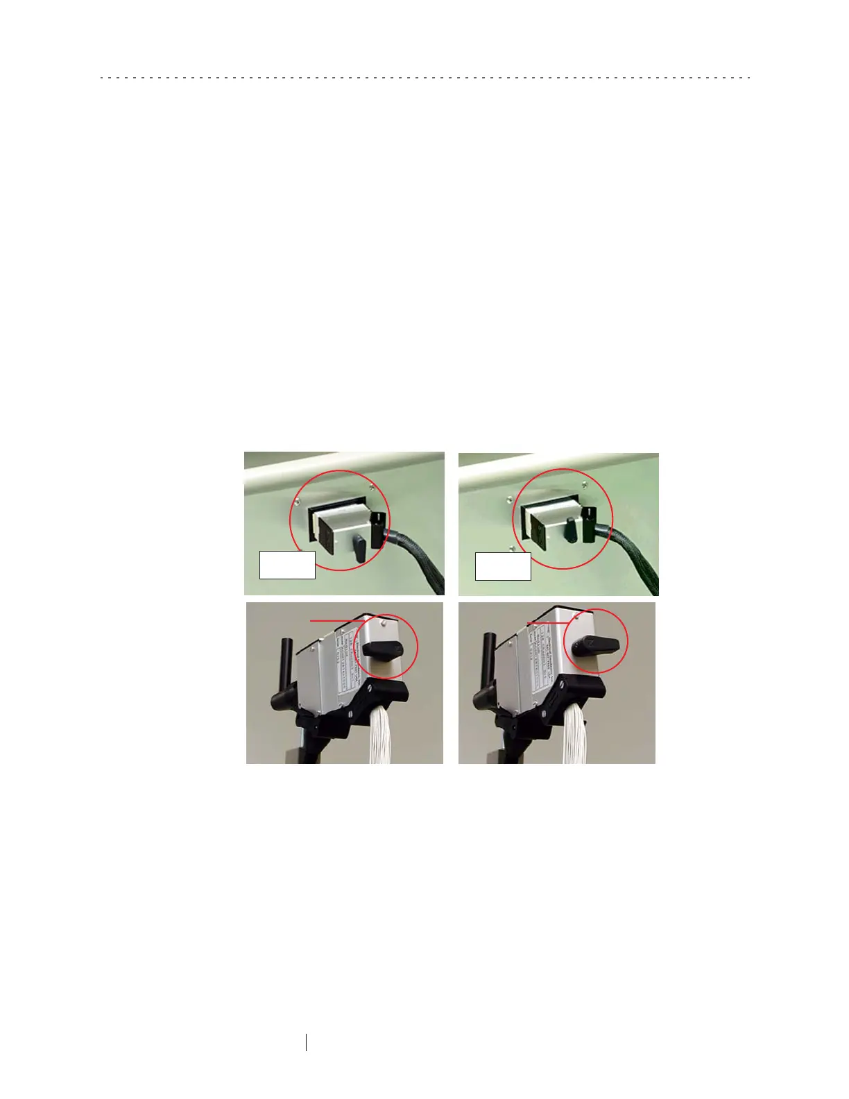
Making and Breaking Hypertronics Connections
The Hypertronics connector can be inserted or removed when the lever is in the
released position. As shown in the top pictures of Figure 8-3, the lever points
downward when the connector to the Net Amps 200 is in its released position and
upward when it is locked. For the connector to the GSN, the lever points to the left
when it is released and to the right when it is locked (bottom pictures of Figure 8-3).
When the lever is locked, the connector cannot be inserted or removed from its
connector.
Note: Before inserting a Hypertronics plug, examine its pins to make sure that none are
bent. Inserting a connector with a bent pin can cause the pin to be completely bent over
and in need of replacement.
Figure 8-3. Hypertronics plug released (left) and locked (right)
Released
Locked
Locked
Released